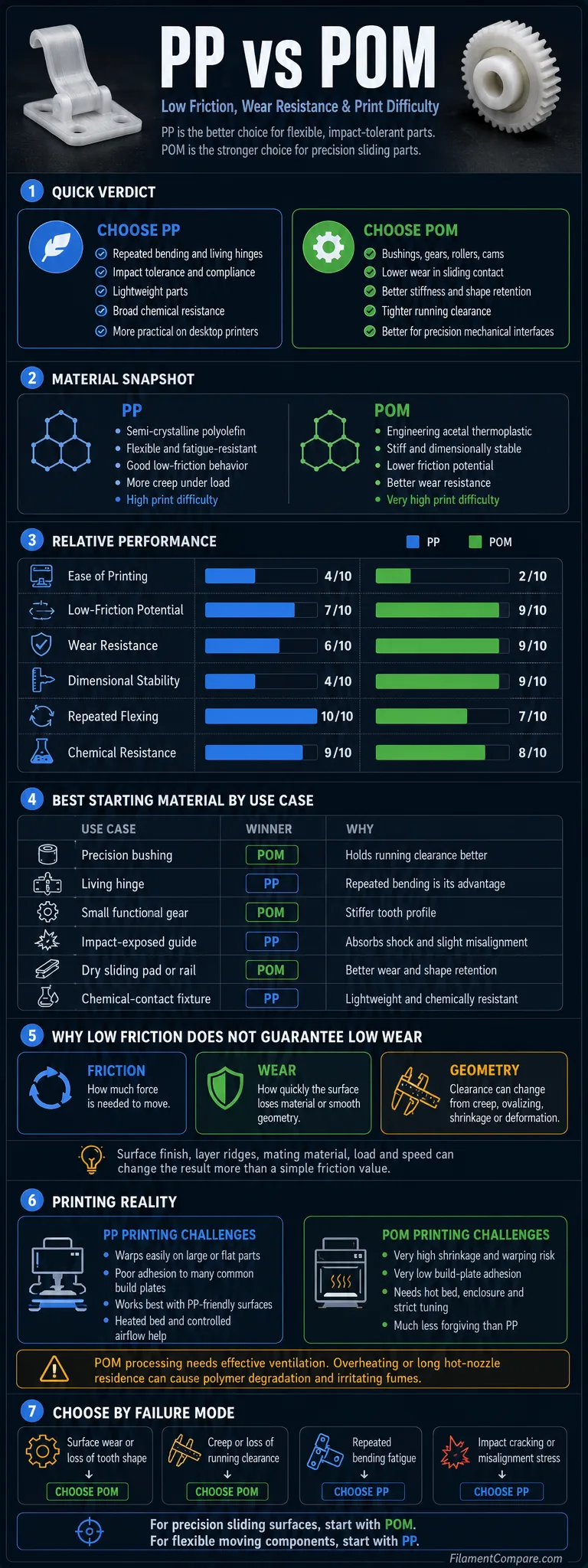
PP is the more flexible, fatigue-resistant option, while POM provides the stiffer and more dimensionally stable sliding surface. POM is usually the stronger starting point for precision bushings, gears, rollers, and guides, but it is also much less forgiving to print. PP fits moving parts that must bend, absorb impact, resist chemicals, or tolerate slight misalignment.
The Practical Choice
Choose POM when low wear, controlled running clearance, tooth-profile retention, and resistance to deformation matter more than printing convenience.
Choose PP when the part must flex repeatedly, survive impacts, remain lightweight, or operate in a chemically demanding but relatively low-load mechanism.
There is no universal winner. The better material is determined by how the part is expected to fail: surface wear, creep, fatigue, heat buildup, layer separation, or loss of tolerance.
Precision Bushings
POM
Its higher stiffness helps the bore retain a more predictable running clearance.
Living Hinges
PP
Repeated bending is one of PP’s clearest mechanical advantages.
Dry Sliding Surfaces
POM
It combines low friction with better resistance to wear and shape change.
Impact-Exposed Mechanisms
PP
Its flexibility and toughness help it absorb shock without requiring a rigid contact geometry.
Small Functional Gears
POM
Stiffer teeth are less likely to deflect and alter the intended contact pattern.
Chemical-Contact Guides
PP
PP is often selected where low density and broad chemical resistance are useful.
Tight Running Clearance
POM
Lower creep and better dimensional retention make it the more controlled option.
Ordinary Desktop Printers
PP
It remains tuning-sensitive, but POM adds narrower thermal limits and stricter ventilation needs.
| Comparison Point | PP | POM | More Suitable Choice |
|---|---|---|---|
| Polymer family | Semi-crystalline polyolefin | Semi-crystalline engineering acetal; available as homopolymer and copolymer grades | Application-dependent |
| General print difficulty | High | Very high | PP |
| Typical nozzle guidance | Often about 205–220 °C for UltiMaker PP[b]; other formulations vary | One commercial filament sheet lists 210–250 °C, but the safe ceiling must follow the exact grade | Brand-dependent |
| Typical bed guidance | Often about 85–100 °C for UltiMaker PP | About 110 °C on one commercial POM filament sheet; surface choice remains important | Grade-dependent |
| Enclosure | Helpful for larger parts and stable cooling | Strongly recommended for thermal control, with suitable exhaust or ventilation | PP |
| Build plate adhesion | Low adhesion to many common surfaces; PP-compatible surfaces work better | Very low adhesion to many ordinary build surfaces | PP |
| Warping tendency | High, especially on broad or long parts | Very high and often accompanied by dimensional shrinkage | PP |
| Low-friction behavior | Good, especially in flexible and lightly loaded mechanisms | Usually better suited to controlled sliding and bearing surfaces | POM |
| Wear resistance | Useful under light or moderate loads, but deformation may alter contact | Usually stronger for repeated sliding when surface finish and geometry are controlled | POM |
| Stiffness | Lower; the contact surface can deflect under load | Higher; the contact shape is retained more effectively | POM |
| Repeated bending | Excellent fit for living hinges and flexible joints | Useful fatigue resistance, but not the natural choice for thin living hinges | PP |
| Creep under sustained load | More likely to alter clearance over time | Usually better at retaining mechanical geometry | POM |
| Moisture behavior | Low moisture uptake; drying demand is generally limited | Low moisture pickup compared with many engineering polymers; spool condition still matters | Both |
| Chemical resistance | Broad chemical resistance in many ordinary applications | Good resistance to many solvents, fuels, and chemicals, with grade-specific limits | Exposure-dependent |
| Printed surface behavior | Softer surface can conform slightly but may smear or deform under pressure | Harder sliding surface, though layer ridges can still increase drag and wear | POM |
| Main limitation | Creep, softness, warping, and loss of tight tolerance | Severe print sensitivity, shrinkage, bed adhesion, and overheating risk | Different limitations |
This PP and POM comparison combines manufacturer material guidance, filament processing documents, and established engineering trends; actual results can shift with grade, additives, color, print direction, surface finish, moisture condition, and slicer settings.
Material Profiles for Moving Parts
PP Sliding-Part Profile
- Polymer type: Semi-crystalline polyolefin
- Print difficulty: High
- Nozzle range: Commonly low-to-mid 200 °C range; formulation-dependent
- Bed range: Usually requires a heated, PP-compatible build surface
- Enclosure: Helpful for larger parts
- Drying: Usually less demanding than nylon, though contaminated or poorly stored filament can still print inconsistently
- Typical behavior: Lightweight, tough, flexible, fatigue-resistant, and chemically resistant
- Best use cases: Living hinges, flexible guides, clips, low-load sliders, chemical-contact fixtures, and impact-tolerant components
UltiMaker describes its PP as low-friction, highly tough, and resistant to repeated bending, with a published thermal-resistance value of 99 °C for that specific formulation[a].
POM Sliding-Part Profile
- Polymer type: Polyoxymethylene engineering thermoplastic
- Print difficulty: Very high
- Nozzle range: Must follow the filament maker’s restricted processing window
- Bed range: Usually requires a hot bed and a specially selected contact surface
- Enclosure: Recommended for controlled cooling; ventilation remains necessary
- Drying: Low moisture pickup, with preparation based on the spool maker’s instructions
- Typical behavior: Stiff, hard, dimensionally stable, low-friction, and wear-resistant
- Best use cases: Bushings, gears, rollers, spacers, cams, sliding blocks, and precision mechanical interfaces
Delrin identifies low friction, wear resistance, high stiffness, low moisture pickup, and dimensional stability as defining POM advantages for gears and other mechanical components[c].
Relative Performance for Printed Mechanisms
Ease of Printing
Low-Friction Potential
Wear Resistance
Dimensional Stability
Repeated Flexing
Chemical Resistance
Tolerance Retention Under Load
The meter values are relative indicators for printed-part selection rather than fixed laboratory ratings. Filament grade, additives, pigment, print orientation, wall count, infill, surface condition, load, speed, and mating material can change the result.
Why Lower Friction Does Not Guarantee Lower Wear
Friction describes the resistance to movement between two surfaces. Wear describes how quickly those surfaces lose material, polish, score, deform, or change dimension. A part can slide easily during its first test and still develop excessive clearance after repeated cycles.
POM usually offers the stronger combination of low sliding resistance and controlled contact geometry. Its stiffness helps a bushing, gear tooth, or rail pad maintain the shape used to distribute the load.
PP can also provide a low-friction surface, but its lower stiffness changes how the load is carried. The material may flex around a shaft, spread the contact zone, or temporarily conform to a slightly misaligned rail. That behavior can be useful under light loads. Under sustained pressure, the same flexibility may reduce clearance or produce uneven contact.
Friction Failure
The mechanism requires too much force to start or continue moving.
Wear Failure
The sliding face loses material, becomes rough, or creates debris.
Geometry Failure
The part creeps, ovalizes, shrinks, or changes clearance even before heavy surface wear appears.
A single coefficient-of-friction value cannot predict every mechanism. Celanese notes that friction and wear figures are not pure material constants: they depend on the sliding partner, load, surface, motion, speed, and test arrangement. Its material guidance also separates standard POM from grades modified with PTFE, silicone oil, waxes, or other tribological additives[d].
The Mating Surface Changes the Result
A printed polymer sliding on polished steel does not behave like the same polymer sliding on aluminum, rough steel, another polymer, or a printed surface. A rough shaft can act as an abrasive tool. A very smooth but poorly matched polymer pair may develop stick-slip, noise, or material transfer.
The operating environment also matters. Dust can turn a low-friction interface into an abrasive contact. Lubricant can reduce drag and heat, but it may collect contamination or prove incompatible with one of the materials. A dry-running result should not be applied automatically to a lubricated assembly.
PP Slides by Flexing; POM Slides by Holding Its Shape
The largest practical difference is not simply surface slipperiness. It is how each material responds when pressure is applied to that surface.
How PP Carries Contact Loads
PP is relatively compliant. A PP guide can deflect around a rail or accommodate a small assembly error without creating the sharp local stress that a harder material might experience. This makes PP useful for flexible sliders, snap-on guides, low-force clips, and mechanisms where slight deformation is intentional.
The limitation appears when the mechanism depends on a fixed gap. A PP bore can become tighter under compression, wider after long-term loading, or slightly oval after repeated movement. The visible surface may show little damage even though the mechanism no longer moves as designed.
How POM Carries Contact Loads
POM is stiffer and better suited to maintaining a defined tooth profile, roller diameter, or bearing clearance. Under the same moderate load, a POM contact surface usually changes shape less than a PP surface.
This does not make POM immune to design errors. A rigid printed bushing with insufficient clearance may bind as soon as the bore shrinks or the shaft warms. POM also tolerates alignment errors less gracefully than a flexible PP guide. The design needs enough clearance to account for printing variation, thermal expansion, surface texture, and the expected operating temperature.
Failure Mode Matters More Than Material Reputation
- If the expected failure is surface wear, POM is usually the stronger starting point.
- If the expected failure is repeated bending fatigue, PP is usually the stronger starting point.
- If the expected failure is creep or loss of clearance, POM has the advantage.
- If the expected failure is impact cracking or misalignment stress, PP may be more forgiving.
Printed POM Is Not Machined Acetal
POM is widely associated with machined and injection-molded gears, bushings, rollers, and precision components. Those parts are relatively dense and homogeneous. An FFF part introduces layer boundaries, extrusion variation, internal voids, a seam, and a staircase texture on curved surfaces.
The printed part may therefore perform far below the resin’s published potential. A POM bushing with a rough bore can produce more drag than expected. A gear can retain a stiff tooth profile but still fail at a weak layer boundary. A roller can use an appropriate resin yet vibrate because it is not round.
Material data should be treated as a starting condition, not a finished-part guarantee. The actual moving surface is created by the printer, toolpath, layer height, seam placement, extrusion consistency, and any later machining.
Part Density and Layer Bonding
Low infill may be acceptable for a housing, but a sliding component often needs solid walls around the contact zone. A bore supported by sparse internal structure can flex even when the polymer itself is stiff. More perimeters, sufficient top and bottom thickness, and a dense region around fasteners or bearings can matter more than a high global infill percentage.
Layer orientation should follow the expected force path. A gear printed flat usually keeps the tooth profile within the layer plane, while a gear printed upright may place more of the tooth-root load across layer boundaries. A bushing must also resist hoop stress, axial force, and any press-fit load without opening along a weak plane.
POM-H and POM-C Are Not Interchangeable Labels
POM homopolymer and POM copolymer have related but different performance profiles. Commercial filaments may also contain stabilizers, lubricating additives, pigments, or processing modifiers. A result obtained with one POM spool should not be treated as a universal value for every acetal filament.
The same caution applies to PP. Homopolymer, copolymer, low-warp blends, glass-filled grades, and carbon-filled grades can differ in stiffness, impact response, shrinkage, bed adhesion, and wear behavior. Reinforcement may stiffen a PP part, but it can also make the printed surface more abrasive to the mating component.
Surface Finish Can Override the Resin Choice
Layer ridges can behave like a fine file when they move repeatedly across a shaft or rail. The effect becomes more noticeable with high contact pressure, a rough mating surface, or motion that crosses the layer texture.
A seam placed inside a bushing creates one raised line that may carry much of the load. Over-extrusion can produce an uneven bore. Under-extrusion can leave weak grooves that collect debris. A low layer height may improve the contact texture, but it does not correct an undersized hole or unstable thermal shrinkage.
Bores and Bushings
Printed holes commonly finish smaller than their CAD diameter. For a low-friction bushing, it is usually better to print a controlled allowance and finish the bore with a drill, reamer, or other suitable tool. This creates a more circular surface and removes the worst layer ridges.
POM is especially suitable for this approach because it is commonly machined in conventional forms. PP can also be finished, but its flexibility may make precise cutting more difficult unless the part is supported correctly.
Gears and Tooth Contact
POM’s stiffness favors tooth-profile retention, but an inaccurately printed tooth still produces poor meshing. Elephant’s foot, seam placement, insufficient backlash, and rough flanks can increase noise and heat. PP teeth may run quietly under light load, though deflection becomes a concern as torque rises.
Rollers and Linear Guides
Roundness, concentricity, and shaft alignment can dominate roller performance. POM is usually the better resin when diameter retention matters, but a poorly centered bore will still create cyclic loading. PP is more suitable where a soft contact and slight compliance are useful, rather than where the roller must maintain a precise circular profile.
Design allowance: Do not apply one universal shrinkage percentage to every PP or POM model. Print a short tolerance sample using the intended spool, printer, orientation, wall count, and cooling setup before committing to the full component.
A Practical Wear Test Before Production
A simple comparative test can reveal more than a generic material ranking. Print PP and POM samples with the same nominal geometry, then run them against the same shaft under equal load, speed, travel, and cycle count.
Record Before the Test
- Bore or slider dimensions
- Part mass
- Surface appearance
- Starting movement force
- Initial running clearance
- Shaft surface condition
Record After the Test
- Change in clearance
- Change in mass
- Surface polishing or scoring
- Polymer transfer to the shaft
- Operating temperature
- Noise, binding, or stick-slip
A short hand-sliding test is not enough. Some parts feel smooth at first and later fail through heat buildup, surface transfer, creep, or growing clearance. Testing should continue long enough to expose the expected failure mode.
The Print Failures Are Different
Why PP Warps and Releases From the Bed
PP has low surface energy and does not bond reliably to many ordinary build surfaces. A first layer may appear acceptable and then release when later layers contract. Wide corners, long straight walls, thick-to-thin transitions, and large flat footprints increase the stress pulling against the bed.
A PP-compatible build surface is usually more dependable than simply increasing bed temperature. Brims and rounded corners can help, but they do not replace correct surface chemistry. Draft protection and stable room conditions become more important as the part grows.
Cooling must be balanced. Too much airflow can increase shrinkage and corner lift. Too little cooling may reduce bridge quality and soften small details. The appropriate fan setting depends on part geometry and the filament formulation.
Why POM Is Less Forgiving
POM combines high crystallinity with low adhesion to many common surfaces. The result is a material that can pull strongly against the build plate while offering limited chemical grip to that plate. Even when the first layer remains attached, internal stress can distort bores, bend long components, or split higher sections.
A Monocure POM filament sheet lists a 210–250 °C print range, a 110 °C bed, slow-to-moderate speeds, and a recommended heated chamber for that particular product[e]. These figures should not be copied to an unrelated POM filament because formulation and thermal-stability limits differ.
POM Thermal Safety
POM must not be treated like an ordinary high-temperature filament. Excessive temperature or prolonged residence in a hot nozzle can degrade the polymer and release irritating formaldehyde-containing fumes.
Celanese states that Celcon POM should not be heated above 238 °C and should not remain above 193 °C for more than 15 minutes without purging in its stated processing context[f]. The filament manufacturer’s current safety data sheet and processing limits take priority for the exact spool being used.
- Use effective ventilation or externally exhausted local extraction.
- Do not rely on a closed enclosure as a substitute for ventilation.
- Prevent long pauses with POM sitting in a hot nozzle.
- Do not exceed the grade-specific temperature ceiling to improve flow.
- Stop the process if abnormal odor, discoloration, or decomposition is suspected.
- Do not mix POM with incompatible materials left in the hotend; purge according to the equipment and material instructions.
Printer Requirements
PP can often be attempted on a capable desktop printer with a heated bed, a suitable build surface, controlled airflow, and a well-tuned material profile. POM calls for a more controlled setup: stable enclosure temperature, a bed capable of the required range, carefully selected adhesion method, accurate hotend control, and appropriate fume management.
A printer being able to reach the nozzle temperature does not mean it is prepared for POM. Thermal overshoot, long hotend residence time, an unvented enclosure, unstable bed temperature, and unsuitable hotend materials can all make the process less predictable.
Where PP and POM Fit in Real Mechanisms
| Use Case | Better Starting Material | Reason |
|---|---|---|
| Precision dry-running bushing | POM | Better stiffness, wear behavior, and retention of running clearance |
| Low-load flexible slider | PP | Can accommodate slight misalignment and elastic movement |
| Small functional gear | POM | Stiffer teeth retain the intended contact shape more effectively |
| Living hinge | PP | Excellent resistance to repeated bending in a suitable hinge design |
| Linear rail wear pad | POM | Lower deformation supports more predictable contact pressure |
| Impact-exposed guide | PP | Flexibility and toughness can absorb shock and assembly error |
| Precision roller | POM | Better diameter and shape retention, especially when finish-machined |
| Chemical-contact fixture | PP | Broad chemical resistance and low density, subject to the exact chemical and temperature |
| Snap-on moving clip | PP | More suitable for elastic deflection during installation and use |
| Cam or indexing component | POM | Stiffness and wear resistance help preserve the contact profile |
| Soft-contact low-noise mechanism | PP or modified POM | PP provides compliance; tribologically modified POM may control friction and squeak more effectively |
| Large flat printed mechanism plate | Neither is easy | Both can warp; design segmentation or another material may be more practical |
| Unventilated occupied room | PP | POM processing adds a thermal-decomposition and ventilation concern |
| Replaceable insert in an easy-to-print housing | Machined or molded POM insert | A separate wear insert can provide a smoother and more predictable contact surface |
Lubrication and Modified Grades Change the Comparison
Low-friction does not automatically mean lubrication-free. A compatible lubricant can reduce startup resistance, operating heat, noise, and surface damage. It can also attract abrasive dust or interact poorly with plastics, seals, coatings, and nearby components.
Standard POM should not be confused with a wear-modified POM compound. Some grades include PTFE, silicone oil, waxes, molybdenum disulfide, or other additives selected for a certain mating surface and load condition. These additives can reduce friction or noise, but they may also alter strength, impact response, weld-line behavior, or regulatory suitability.
Filled PP requires the same caution. Glass or carbon reinforcement can increase stiffness and reduce some deformation, but exposed fibers may abrade the opposing shaft or rail. A reinforced grade should not automatically replace unfilled PP in a sliding pair.
Questions to Settle Before Selecting a Lubricant or Modified Grade
- Is the mating surface steel, aluminum, brass, POM, PP, or another polymer?
- Is the motion continuous rotation, oscillation, or short linear travel?
- Will dust, water, cleaning agents, or food-contact requirements affect lubricant selection?
- Is low noise more important than maximum wear life?
- Can the wear component be replaced independently?
- Does the filament contain fibers or sliding additives that change the expected surface behavior?
Where Each Material Fits Better
Choose PP When
- The component must bend repeatedly without using a separate hinge.
- Impact absorption is more important than maintaining a rigid bearing surface.
- The mechanism includes minor alignment variation.
- Low weight is valuable.
- The part needs broad chemical resistance within PP’s grade-specific limits.
- The sliding load is light enough that creep and surface deformation can be controlled.
- The printer setup is not prepared for the tighter safety and thermal demands of POM.
PP Has Limits When
- The running clearance must remain tightly controlled under sustained load.
- Gear teeth or cams must retain an accurate contact profile.
- A soft bore could deform around the shaft.
- Large flat geometry makes warping difficult to control.
- The part will operate near a temperature where the chosen PP grade loses useful stiffness.
Choose POM When
- The part is a bushing, gear, roller, cam, spacer, or sliding block.
- Low wear and stable geometry are both required.
- The contact surface can be reamed, drilled, turned, or otherwise finished.
- The mechanism uses a defined running clearance.
- The part will see repeated sliding rather than repeated hinge-like bending.
- The printer, build surface, enclosure, and ventilation are prepared for the selected POM grade.
POM Has Limits When
- The workspace lacks effective ventilation.
- The printer cannot maintain a stable bed and chamber environment.
- The print requires long pauses with material held in the hotend.
- The component is large, flat, or very sensitive to shrinkage distortion.
- The design expects the material to absorb misalignment through elastic deformation.
- A ready-made or machined acetal insert would be simpler and more repeatable.
When Neither Filament Is the Practical Option
Printing the entire component from PP or POM is not always the most reliable construction method. A housing can be produced from an easier filament while the actual sliding interface uses a replaceable POM insert, commercial bushing, bearing, sleeve, or wear strip.
This mixed-material approach is worth considering when the contact surface needs tighter tolerances than the printer can provide. It also allows the worn part to be replaced without discarding the full assembly.
Consider Another Construction When
- The part carries high bearing pressure or runs continuously at speed.
- Failure could create a safety hazard.
- The surface requires a tolerance that cannot be measured and corrected after printing.
- The mechanism operates at a temperature outside the useful range of the chosen grade.
- The application requires certified material traceability or regulated contact approval.
- A standard industrial bushing is available at lower cost and higher consistency.
- The mating surface would be damaged by fiber-filled filament.
Material Selection Matrix
Choose by the Expected Failure
Choose POM if the part is expected to fail through wear, loss of tooth shape, bore deformation, increasing clearance, or unstable sliding geometry.
Choose PP if the part is expected to fail through repeated bending, impact, snap-fit stress, or small alignment errors that require elastic compliance.
Choose a separate POM wear insert when the housing is easy to print but the contact surface needs machining-level smoothness or replaceability.
Choose neither when the load, speed, temperature, safety role, or tolerance exceeds what an FFF polymer contact can reliably provide.
POM is the stronger material choice for a precision sliding surface. PP is the stronger design choice for a flexible moving component. The final decision should follow the part’s load path, mating surface, thermal environment, expected cycle count, and available printer controls.
Common PP and POM Questions
Is POM Always More Slippery Than PP?
No. POM generally has the stronger reputation for controlled sliding and wear applications, but the actual result depends on grade, additives, surface finish, mating material, pressure, speed, temperature, and lubrication. A rough printed POM surface can move less smoothly than a properly finished PP surface.
Which Material Is Better for a Printed Bushing?
POM is usually the better starting point for a bushing that must retain a defined clearance. PP can work in lightly loaded or flexible guides, especially where small alignment errors need to be absorbed.
Can PP Be Used for Gears?
Yes, particularly for lightly loaded, quiet, or impact-tolerant mechanisms. POM is generally more suitable when the gear must retain tooth geometry, backlash, and efficiency under repeated load.
Does POM Need Lubrication?
Not in every application. Standard and wear-modified POM grades may operate dry under suitable loads, speeds, and mating conditions. Lubrication can still reduce heat and wear, but compatibility with the polymers and operating environment must be confirmed.
Can POM Be Printed Safely on a Home Printer?
Only when the exact filament instructions, temperature limits, printer capabilities, ventilation, and hotend procedures are understood and followed. A closed consumer printer without effective exhaust should not be assumed to provide sufficient protection from decomposition fumes.
Should a Printed Bore Be Used Directly?
It can be used directly for low-demand parts, but a precision sliding bore usually benefits from a printed machining allowance followed by drilling, reaming, or another controlled finishing operation. Test the final clearance under the expected operating temperature and load.
Technical References
- [a] S series PP – UltiMaker (Used for PP fatigue behavior, toughness, low-friction positioning, living-hinge suitability, and formulation-specific thermal data.)
- [b] How to print with UltiMaker PP (Used for manufacturer-specific PP nozzle and build-plate temperature guidance.)
- [c] Delrin®: The High-Performance Acetal Resin (Used for POM stiffness, low friction, wear resistance, low moisture pickup, dimensional stability, and mechanical use cases.)
- [d] Hostaform® POM Product Manual (Used for system-dependent friction and wear behavior, mating-surface effects, and tribologically modified POM grades.)
- [e] POM FILAMENT (Used for one commercial POM filament’s stated print temperature, bed temperature, print speed, chamber recommendation, and physical-property context.)
- [f] Celcon® POM (Used for thermal-processing limits, residence-time precautions, degradation risk, and formaldehyde-related processing safety.)
