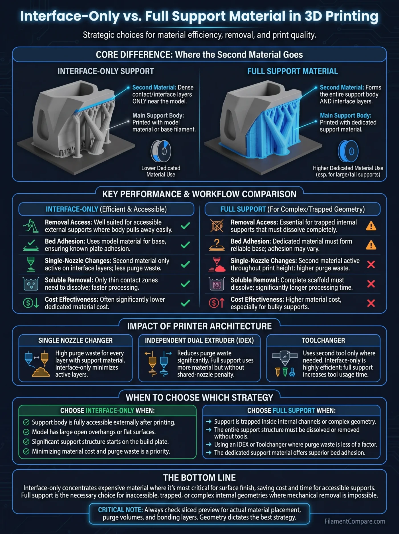
| Decision Area | Interface-Only Support | Full Support Material |
|---|---|---|
| Second material is used for | Dense contact/interface layers near the model | Support body plus contact/interface layers |
| Main support body | Usually printed with the model material or another base material | Printed with the dedicated support material |
| Dedicated support filament consumption | Usually lower | Usually higher, especially with tall or bulky supports |
| Supported-surface potential | Can be very good when the interface material, gap, density, and cooling are tuned | Can be very good; using the second material through the whole tower does not by itself improve the contact surface |
| Accessible external supports | Well suited when the remaining support body can be pulled away | Often uses more dedicated material than the geometry requires |
| Trapped internal support | Limited if the non-removable support body cannot leave the part | Well suited when the entire support must dissolve or otherwise be removed without tool access |
| Support starting on the build plate | Lets the base use a material with known plate adhesion | The dedicated support material must form a reliable support base or use another validated strategy |
| Single-nozzle material changing | Second material is needed only on interface-bearing layers, although purge is still required | Second material may be active through much more of the print height |
| Independent dual nozzle / toolchanger | Still saves dedicated support material | Extra material remains the main cost difference because melt-path purging is greatly reduced or absent |
| Soluble-material removal | Only the soluble contact zones need to dissolve | The complete soluble scaffold must be removed |
| Main reason to choose it | Clean separation without filling the entire support structure with the second material | The support body itself is inaccessible after printing |
This comparison of interface-only support and full support material uses manufacturer documentation, current slicer behavior, and established FFF support principles; the patterns describe normal workflow differences, while actual material use, print time, purge volume, and surface finish vary with geometry, printer architecture, filament pairing, and slicer settings.
The difference is simple in geometry but large in practice. With interface-only support, the second filament is placed mainly where the support meets the printed part. The bulk of the scaffold stays in the model material or another designated base filament. With full support material, the dedicated support filament also forms the towers, branches, walls, or other structure underneath that interface.
If the support body can be reached and removed after printing, using the second material only at the interface often captures most of the separation benefit while consuming less dedicated support filament. If that support body will be trapped inside the finished geometry, dissolving or releasing only the contact layer is not enough. The inaccessible scaffold must also have a viable exit or removal mechanism.
Terminology matters: “full support material” means the dedicated second material is assigned to the support body as well as the interface. It does not mean the slicer uses 100% support density.
The Support Body and the Interface Perform Different Jobs
A conventional support structure is not one uniform mass. The lower portion is generally a relatively sparse support body whose job is to carry load and reach the required height. Near the model, the slicer can create a denser support interface that gives the first supported model layers a more continuous surface beneath them.
- Support body
- The larger scaffold below or beside the part. It provides height, stiffness, and a path from the bed or another model surface to the supported region.
- Support interface
- The denser transition region closest to the printed part. It influences contact quality, separation, and the condition of the downward-facing model surface.
- Interface-only material assignment
- The second filament is reserved mainly for the interface while another material forms the support body.
- Full support material assignment
- The second filament forms both the body and the interface.
PrusaSlicer makes this distinction explicit with SOLUBLE FULL and SOLUBLE INTERFACE configurations. In the full configuration, soluble material forms the whole support structure. In the interface configuration, it is concentrated in the denser layers between the support structure and the model.[a]
This distinction also explains why replacing every support line with an expensive support filament is not automatically necessary. The lower scaffold does not touch the final supported face. Its primary task is structural.
Geometry Decides Whether Interface-Only Support Is Enough
The most useful question is not whether the support material is soluble, breakaway, or expensive. Ask what happens to the support body after the interface has been removed.
Consider a large horizontal overhang with open sides. A soluble or low-bond interface can release the model cleanly, while the ordinary support body can then be pulled straight out. There is little reason for the entire tower to dissolve if it remains fully accessible.
Now put the same support structure inside a curved duct with a small entrance. The contact layer may dissolve perfectly, yet a large model-material scaffold can remain behind the bend. It is loose, but still trapped. Interface-only support has solved the bond, not the extraction problem.
- Open underside: interface-only support is often practical because the base can be removed mechanically.
- Wide cavity with a direct opening: interface-only may still work if the support body can leave in pieces.
- Curved internal passage: full removable or soluble support may be needed because the scaffold cannot follow a straight extraction path.
- Captured mechanism: support around gears, hinges, or enclosed moving parts may require the entire inaccessible portion to be removable without tools.
- Sealed cavity: neither strategy automatically solves the design. A soluble scaffold still needs liquid access and a route for dissolved material to leave.
A dissolved interface does not make a trapped support body disappear. Internal access and drainage should be evaluated before deciding how much of the support structure needs the second material.
Surface Finish Is Determined Near the Model
The underside of a supported surface responds most directly to what happens in the final few layers below it. Interface density, top contact distance, layer height, cooling, interface pattern, extrusion consistency, and material compatibility all affect how well the first model layer is held.
Changing the material at the bottom of a 60 mm support tower does not directly change the texture of the model surface 60 mm above it. If two strategies create the same stable interface at the same contact distance, printing the lower support body from the dedicated material does not automatically create a smoother underside.
Why a Dedicated Interface Can Use a Tighter Contact
Same-material supports normally need controlled separation so the model does not fuse strongly to the support. A compatible soluble or release interface can sometimes operate with a zero or near-zero top contact distance because the two regions are intended to separate by dissolution or low inter-material bonding rather than by an air gap.
That tighter contact can give the first supported layer a flatter base. It is not a universal setting. The correct distance still depends on the exact materials and slicer profile.
Bambu Lab takes the interface-specific concept further with its Support for PLA/PETG material, which the manufacturer identifies for support-interface use rather than the support base. Its published printing guidance also directs users to select it as the Support/Raft Interface material and advises against using it for the base of tree supports.[b]
Interface-Only Can Save More Than Support Filament
The obvious saving is the amount of dedicated material. A thin interface may represent only a small fraction of the total scaffold volume, while full support assigns the second filament to every trunk, branch, grid line, or tower in that support region.
Material volume is only one part of the calculation. On a single-nozzle material-changing printer, each transition can also require unloading, loading, melt-zone flushing, and a purge or wipe structure. Contamination matters because residue from one polymer may change how the interface releases, dissolves, or bonds to the model.
Prusa’s MMU guidance gives a useful hardware-specific example: its documented default is 140 mm³ for a filament change, while the manufacturer recommends at least 200–240 mm³ when using water-soluble supports and notes that more may be required if residue remains.[c] These numbers are not universal purge settings; they illustrate why the transition cost can become material in a support-heavy multi-material print.
The Printer Architecture Changes the Economics
| Printer Architecture | Interface-Only Effect | Full Support Effect |
|---|---|---|
| Single nozzle with automatic material changes | Limits second-material extrusion to selected interface regions, though those layers still need flushing and switching | Dedicated support material can remain active across much more of the supported print height |
| Independent dual nozzle / IDEX | Reduces dedicated support consumption without sharing the same melt chamber | Higher dedicated material use, but transition waste may be far lower than on a single-nozzle changer |
| Toolchanger | Uses the second tool only where its interface material is needed | Uses the support tool for both scaffold and interface; tool changes still cost time but do not require the same full melt-zone purge |
A slicer’s final estimates are therefore more useful than a generic claim that interface-only is “X percent cheaper.” Two models with the same supported surface area can produce very different support heights, material-change counts, and purge totals.
A Better Cost Comparison
Slice the same model twice and compare the complete material totals. For each material, use:
Material cost = filament used in grams × spool price per kilogram ÷ 1,000
Include purge, prime-tower, and other disposable extrusion when the slicer reports it. Then compare total material cost, dedicated support grams, estimated print time, and the amount of support that must be removed after printing.
Support Starting on the Build Plate Changes the Decision
Full support material can place the dedicated filament directly on the build surface. That means bed adhesion becomes part of the support-material decision, even if the material bonds perfectly to the model polymer.
Prusa’s soluble-support documentation notes that its PVA+ and BVOH workflow can have weaker adhesion to certain PEI sheets than when those materials are printed onto PLA or PETG, and it recommends the soluble-interface approach when substantial support begins on the build plate.[d]
This is an important structural distinction. In an interface-only arrangement, the model material can form the footprint, lower tower, or tree trunk that needs reliable bed contact, while the second material appears only near the supported surface. Full support asks one filament to satisfy both jobs.
The Material Boundary Inside the Support Also Matters
Interface-only support introduces an extra material junction: support body → interface material → model. That junction must remain stable long enough to survive accelerations, nozzle passes, cooling, and the weight of the layers printed above it.
If the interface material bonds too weakly to the support body, a small interface island can shift or peel before the model reaches it. If the pairing bonds too strongly at the model side, removal becomes less clean. Purge contamination can change either behavior.
The risk is especially relevant for small support tips, narrow tree branches, isolated interface islands, and tall supports with little lateral stiffness. A wide flat interface sitting on a broad support roof has much more contact area than a few millimeters of interface perched on a narrow branch.
Modern Slicers May Add a Bonding Layer Between the Two Materials
“Interface-only” should not be interpreted as a guarantee that every dense interface line is printed from the second filament. The exact transition is slicer-dependent.
Current OrcaSlicer documentation separates the support base filament from the support interface filament and includes an “Avoid interface filament for base” control. Its documented interface transition can retain a base-material bonding layer behind the interface so the dedicated interface material rests on a more continuous compatible surface.[e]
For ordinary multi-material interfaces, the documented OrcaSlicer behavior varies with the selected interface-layer count. A one-layer interface can be entirely interface filament, while larger layer counts can include a base-material layer behind it. Soluble zero-gap interfaces receive separate transition handling.[f]
Check the sliced preview, not only the settings panel. The preview should show which material forms the support base, which material forms the model-facing interface, and where additional bonding or transition layers appear.
Full Soluble Support Creates a Different Removal Workload
Five grams of soluble interface and fifty grams of soluble scaffold are not the same post-processing job. With interface-only support, much of the ordinary scaffold can often be pulled away before the soluble contact material is washed or dissolved. Full soluble support places a larger volume of polymer into the liquid-removal stage.
Thick supports also have interior material that water must reach. Circulation, temperature within the material supplier’s permitted range, support density, water saturation, and the available flow paths around the part affect removal time.
UltiMaker reports a typical 1–8 hour dissolution cycle for its PVA Removal Station and states that the duration depends on the support structure and process conditions.[g] That figure describes UltiMaker’s controlled PVA-removal system rather than every PVA print, but it shows why soluble-support volume should be treated as a post-processing variable as well as a filament-cost variable.
A Soluble Support Still Needs Access to Liquid
Full soluble support is useful for internal channels and captured geometry only when liquid can reach the material and carry dissolved residue away. A narrow opening may be enough for water but still restrict circulation. A completely sealed void has no practical dissolution path after printing.
That makes drainage geometry part of support planning for enclosed parts. The support choice cannot compensate for a cavity that neither tools nor liquid can access.
Full Support Material Does Not Mean One Universal Filament Type
The strategy can be used with water-soluble filaments, purpose-made release materials, or other validated support combinations. What matters is whether the selected material is actually designed to perform the assigned job.
Some support products are meant mainly for the contact interface. Others are suitable for forming larger support structures. A filament sold as a support material should therefore not automatically be assigned to the entire support body. Manufacturer instructions take priority over the generic category name.
The model polymer matters too. Extrusion-temperature compatibility, inter-material adhesion, cooling requirements, bed temperature, chamber conditions, and moisture sensitivity can all affect whether a material pairing remains stable through a long dual-material print.
Four Geometries Produce Four Different Support Decisions
| Print Geometry | Main Constraint | More Suitable Starting Strategy | Reason |
|---|---|---|---|
| Large flat external overhang | Surface finish with full mechanical access underneath | Interface-only | The dense second-material layer can control separation while the ordinary support body remains easy to pull away. |
| Long curved internal duct | Support cannot travel around the bend during removal | Full soluble support in the inaccessible region | Releasing only the contact layer would still leave the bulk scaffold trapped inside. |
| Tall support forest rising from the build plate | Large support footprint and high support volume | Interface-only when the base remains accessible | The model-compatible material can form the large structural base while the dedicated material is concentrated near contact surfaces. |
| Small isolated support islands inside a mechanism | Limited contact area between support body and interface | Depends on material pairing and slicer preview | Interface-only saves material, but tiny cross-material boundaries need enough stability to survive the print. |
Where Each Strategy Can Run Into Limits
| Observed Problem | Interface-Only Explanation | Full Support Explanation |
|---|---|---|
| Support remains inside the part | Non-soluble or non-removable support body may be trapped after the interface releases | Less likely when the entire trapped structure uses a removable material and has a valid exit or dissolution path |
| Interface separates during printing | Cross-material bond between support body and interface may be too weak or too small | Fewer body-to-interface material boundaries when the same support material forms both regions |
| High material cost | Dedicated material is limited mainly to contact regions | Large towers and branches consume the same dedicated material as the interface |
| Large purge structure | Still possible on single-nozzle systems when many layers contain interface material | Can become larger when support material is required across many additional layers |
| Weak support footprint | Base can remain in a material with proven plate adhesion | Dedicated support filament must provide suitable bed adhesion or use a compatible base/raft solution |
| Long dissolving stage | Usually less soluble mass remains after mechanical removal of the base | A larger soluble volume must be exposed to water or the specified removal medium |
The Two Slicer Assignments That Define the Strategy
Most slicers that support multi-material support workflows expose two conceptually separate assignments, even if the labels differ between programs.
- Support base/body material: controls the larger structural scaffold and, in some slicers, the raft or lower support regions.
- Support interface material: controls the denser material nearest the supported model surfaces.
For an interface-only strategy, the base normally stays assigned to the model material, default/current material, or another intentional support-base filament while the interface receives the second material. For full support, both assignments point to the dedicated support material.
Other settings then determine the quality of that arrangement: top contact distance, interface layer count, interface spacing, XY separation, support pattern, cooling, extrusion temperature, purge volume, and support-layer synchronization where required by the printer or slicer.
Those values should not be copied as universal numbers from one material pairing to another. A soluble interface, a purpose-made breakaway interface, and two ordinary polymers used as a release pair can require different contact and purge behavior.
Decision Matrix by Print Condition
| Print Condition | Strategy to Evaluate First | Reason |
|---|---|---|
| All support body is exposed after printing | Interface-only | The second material can be concentrated at the contact surface while the base is removed mechanically. |
| Support body is trapped behind an internal bend | Full removable support | Releasing only the interface does not create an extraction path for the scaffold. |
| Large amount of support begins on the bed | Interface-only if the dedicated material has less suitable bed adhesion | The normal model material can create the structural footprint. |
| Single-nozzle multi-material print with many supported layers | Compare both sliced estimates | Material changes, purge volume, and print time may outweigh the raw support-filament difference. |
| Independent dual-nozzle or toolchanging printer | Decide mainly from support volume and geometry access | The shared-nozzle contamination penalty is reduced, so dedicated support consumption becomes a larger part of the difference. |
| Very small support islands | Check interface stability in preview and test geometry | The body-to-interface bond area can be small even when the overall support volume is low. |
| Smooth supported face with accessible support below it | Interface-only | The interface controls the contact condition without requiring the complete scaffold to use the second filament. |
| Captured gears, enclosed mechanism, or inaccessible internal scaffold | Full soluble/removable support where compatible | The support body itself must leave the part without direct mechanical access. |
For many ordinary external overhangs, interface-only support concentrates the specialized material where it performs its most useful role: between the support structure and the model. Full support material becomes more valuable when the scaffold itself, not merely the contact layer, creates the removal problem.
The final comparison should be made in the sliced model rather than from the support setting name alone. Material totals, tool changes, purge or prime structures, support-body accessibility, bed contact, interface area, and post-processing requirements together describe the real difference between the two strategies.
Technical References
- [a] Prusa Knowledge Base — Water-soluble materials (PVA/BVOH)
- [b] Bambu Lab — Support for PLA/PETG
- [c] Prusa Knowledge Base — Purging volumes for soluble supports
- [d] Prusa Knowledge Base — Water soluble BVOH/PVA material guidance
- [e] OrcaSlicer Documentation — Support Filament Settings
- [f] OrcaSlicer Documentation — Interface Filament Transitions
- [g] UltiMaker — PVA Removal Station
