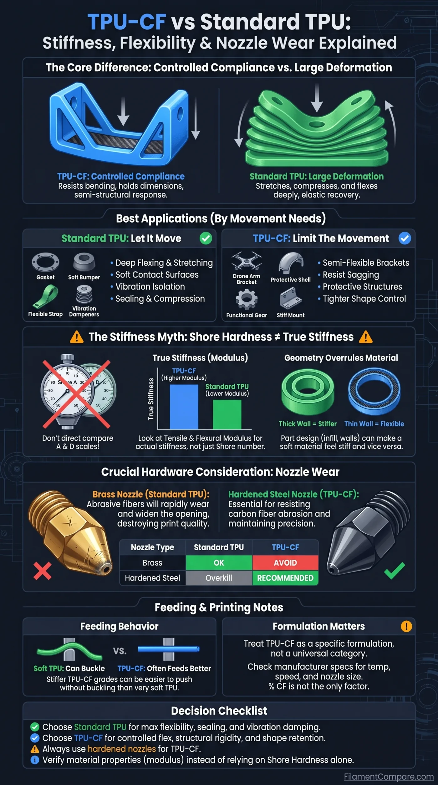
Standard TPU is built around large, recoverable deformation, while TPU-CF trades some of that soft elastomer behavior for higher stiffness, better shape control, and a more structural response. That makes standard TPU the better starting point for parts that need to stretch, compress, or flex deeply, while TPU-CF makes more sense when a part should bend only so far and then resist further deformation. The carbon fiber also changes the hardware requirement: unlike ordinary unfilled TPU, TPU-CF is abrasive to the nozzle.
The Better Fit by Deformation
Choose standard TPU when softness, high deformation, elastic recovery, vibration isolation, sealing, or repeated deep flexing matters most. Choose TPU-CF when the part still needs compliance but should hold dimensions, resist bending more strongly, or behave closer to a semi-structural component. There is no universal upgrade path from TPU to TPU-CF: the useful choice depends on how much movement the finished part should allow.
| Decision Point | Standard TPU | TPU-CF |
|---|---|---|
| Material structure | Unfilled thermoplastic polyurethane formulation | TPU matrix reinforced with short or chopped carbon fibers |
| Typical mechanical feel | Softer, more rubber-like, grade-dependent | More resistant to bending and shape change |
| Large deformation | Usually the better choice | More limited and highly formulation-dependent |
| Stiffness | Ranges from very soft to relatively firm TPU grades | Usually higher than the base TPU used in the formulation |
| Shape retention | Part geometry may deform readily under load | Usually better suited to controlled deformation |
| Elastic use | Well suited to parts intended to stretch, squeeze, or flex repeatedly | Better suited to parts that need flexibility without excessive movement |
| Filament feeding | Soft grades can buckle or deform in the feed path | Stiffer grades may feed more predictably, but printer compatibility still varies |
| Nozzle abrasion | Ordinary unfilled grades are not abrasive in the same way as fiber-filled filament | Carbon fiber makes nozzle wear a hardware consideration |
| Nozzle material | Brass is normally usable | Abrasion-resistant or hardened nozzle recommended |
| Nozzle diameter | Common flexible-filament nozzle sizes are usable when supported by the printer | 0.4 mm can work for some formulations; larger diameters can provide more clogging margin |
| Best starting point | Seals, soft bumpers, flexible straps, vibration parts, compliant covers | Controlled-flex brackets, protective structures, semi-rigid functional parts |
| Main trade-off | More deformation and harder feeding with softer grades | Less deep flexibility plus abrasive-fiber hardware requirements |
Carbon Fiber Changes Soft Flex Into Controlled Compliance
The useful distinction between these materials is not simply “flexible versus rigid.” TPU-CF can still be a flexible filament, but the added fibers restrict how freely the TPU matrix can deform. The resulting part can bend while requiring more force to reach the same deflection, which is useful when uncontrolled flex would compromise alignment, fit, or load support.
This is why TPU-CF is better described as a controlled-compliance material than as a rigid version of TPU. A mounting bracket that needs a small amount of movement without sagging is a very different problem from a gasket that must compress closely against another surface.
Standard TPU: Let the Part Move
- Large bending or squeezing deformation
- Soft contact surfaces
- Vibration isolation
- Compression and sealing behavior
- Flexible straps and strain-relief parts
- Parts designed around elastic recovery
TPU-CF: Limit the Movement
- Semi-flexible brackets
- Parts that should resist sagging
- Protective structures with controlled flex
- Functional parts needing tighter shape control
- Components combining impact response with stiffness
- Applications where ordinary TPU feels too compliant
Even within TPU-CF, however, the label does not define one mechanical class. Fiberlogy currently specifies FiberFlex+CF with 20% carbon fiber and a Shore hardness of 60D, illustrating how far a reinforced TPU formulation can move toward a firmer mechanical response.[b] Another TPU-CF can use a different base polymer, fiber loading, fiber length, or fiber treatment and behave differently.
Shore Hardness Does Not Tell You the Whole Stiffness Story
Shore hardness is useful for classifying elastomer feel, but it should not be treated as a direct stiffness measurement. It measures resistance to indentation under a defined durometer method. Elastic modulus, flexural behavior, tensile response, and the force required to bend a printed part describe different aspects of material behavior.
Do not compare 95A and 60D as if the numbers were percentages on the same scale. ASTM D2240 states that durometer geometry and applied force differ between instrument types and that no simple relationship exists between results obtained with one durometer type and another.[a]
This matters especially in a TPU-CF comparison because many familiar flexible filaments are marketed using Shore A, while some reinforced or harder TPU formulations are specified in Shore D. A lower-looking numerical value on the D scale does not mean the material is softer than a higher numerical value on the A scale.
For engineering comparisons, look beyond the Shore number. Useful data may include tensile modulus, flexural modulus, elongation at break, tensile strength, impact test results, and the conditions under which the specimens were printed. Those properties should also be compared only when the test methods and specimen conditions are compatible.
Why product-to-product comparison needs care: Smart Materials lists INNOVATEFIL TPU CF at 67 Shore D and reports a 181.2 MPa flexural modulus for printed XY specimens. The same page states that its mechanical test specimens were printed with a 0.4 mm nozzle, 100% rectilinear infill, and 0.2 mm layers.[c] Those numbers describe that formulation and test setup; they are not universal TPU-CF specifications.
Part Geometry Can Overrule the Filament Label
A filament can be mechanically stiffer while the finished part remains easy to bend. Wall thickness, section length, perimeter count, infill structure, local cutouts, and print orientation can shift part compliance enough that two objects printed from the same spool feel like different materials.
Thin Wall
A thin TPU-CF shell can still flex readily because the geometry provides little resistance to bending.
Thick Section
Increasing section thickness can turn the same formulation into a much more structural-feeling component.
Sparse Interior
Lower infill or a compliant lattice can preserve movement even when the filament itself is relatively firm.
More Perimeters
Additional walls can increase bending resistance without changing the filament formulation.
Standard TPU follows the same rule. Prusa’s flexible-material guidance specifically notes that increasing infill and perimeters can raise mechanical resistance, while reducing perimeters and top or bottom layers can retain more flexibility.[e] The practical result is that material stiffness and part stiffness are not interchangeable terms.
This distinction is especially useful when standard TPU seems too soft but TPU-CF seems too firm. Before changing material, geometry may provide the missing behavior. A thicker standard-TPU bracket may resist deformation adequately, while a thin or lattice-based TPU-CF structure may retain enough compliance for the same project.
Nozzle Wear Is the Real Hardware Cost of TPU-CF
The largest printer-hardware difference comes from the reinforcement rather than the TPU matrix. Carbon fibers are abrasive, so repeated extrusion through a comparatively soft nozzle can enlarge or alter the nozzle opening. Prusa’s composite-material documentation calls for a hardened nozzle when printing carbon-, glass-, or Kevlar-filled filaments and identifies 0.4 mm as the lowest optimal nozzle diameter for its general fiber-composite guidance.[d]
| Nozzle Type | Standard TPU | TPU-CF | Practical Consideration |
|---|---|---|---|
| Brass | Normally suitable | Not the preferred long-term option | Good thermal conductivity, but comparatively soft against abrasive fiber |
| Stainless steel | Usable | Depends on the nozzle and manufacturer guidance | Do not assume ordinary stainless is equivalent to a hardened abrasive-material nozzle |
| Hardened steel | Usable, usually unnecessary solely for unfilled TPU | Strong general choice | Designed to tolerate abrasive filament better than standard brass |
| Other abrasion-resistant nozzles | Usable where printer-compatible | Potentially well suited | Check hotend compatibility, thermal behavior, and manufacturer instructions |
Is a 0.6 mm nozzle mandatory for TPU-CF?
No. A larger nozzle can reduce flow restriction and give fibers more room to pass, but TPU-CF is not one standardized formulation with one mandatory nozzle diameter. The Smart Materials TPU-CF data above were obtained from specimens printed through a 0.4 mm nozzle. A 0.6 mm nozzle may still be a sensible choice for a specific spool, especially when its manufacturer recommends it or when clogging margin matters more than fine detail.
What does nozzle wear change?
Nozzle wear is more than cosmetic damage. As the outlet geometry changes, extrusion width and flow behavior can drift from the assumptions used by the slicer. First-layer behavior, dimensional accuracy, line consistency, and small details can then deteriorate gradually. This is why the nozzle should be considered a consumable part of the TPU-CF workflow rather than an unrelated printer component.
A Stiffer Filament Can Feed Better, but Fiber Adds New Limits
Very soft TPU can deform before it reaches the melt zone. Under excessive drive-gear pressure or in a poorly constrained filament path, it can buckle, twist, or wrap around the feeding mechanism. Harder TPU grades are generally easier to push because the filament itself resists compression and sideways deformation more effectively.
That gives some TPU-CF formulations an unusual advantage: although the finished material is more specialized, the filament can be mechanically easier to feed than a very soft TPU. Fiberlogy explicitly associates the higher stiffness of its 60D FiberFlex+CF formulation with easier printing compared with softer flexible TPU grades. That does not mean carbon fiber automatically makes every flexible filament compatible with every extruder, Bowden path, or automatic material system.
Printer compatibility remains formulation-specific. “TPU-CF” does not imply AMS compatibility, Bowden compatibility, high-speed capability, or one fixed retraction strategy. Check the actual hardness and the filament manufacturer’s printer guidance rather than treating the CF label as a feed-system specification.
Printing temperatures are equally unsuitable for a universal TPU-CF rule. For example, Smart Materials specifies 215–245°C and 20–35 mm/s for its TPU-CF, while Fiberlogy lists 190–205°C and a maximum recommended speed below 60 mm/s for FiberFlex+CF. Those ranges overlap only partially because the products are different formulations, not because one profile is wrong.
Recent CF/TPU Research Shows Why Fiber Percentage Is Not Enough
Recent research supports treating TPU-CF as a formulation rather than a fixed material category. A 2025 study evaluated CF/TPU formulations containing 0–25% carbon fiber and found its 20% formulation produced higher tensile, compressive, and impact strength than the neat TPU used in that experiment. The authors reported gains of 63.65% in tensile strength, 105.51% in compressive strength, and 93.69% in impact strength under the study’s optimized material and processing conditions.[f]
Those percentages should not be transferred to a commercial spool. They describe one material system, fiber configuration, specimen design, and processing window. Their value for material selection is the broader result: more carbon fiber is not a substitute for a properly engineered formulation.
A 2026 Polymer Composites study adds another layer. Researchers working with 20% short carbon fiber in TPU found that fiber surface treatment and extrusion-induced fiber alignment influenced energy absorption, with different results in axial and transverse directions. In that experimental system, specific energy absorption increased by 114.3% and 193.6% in those respective directions compared with the study’s pure TPU reference.[g]
What the research changes in a buying decision: carbon-fiber percentage alone cannot predict stiffness, impact response, energy absorption, or fatigue behavior. Base TPU chemistry, fiber length, fiber orientation, fiber-to-matrix bonding, print direction, and specimen geometry can all change the result.
Choosing by How the Finished Part Should Move
| Part Requirement | Better Starting Point | Why | Check Before Printing |
|---|---|---|---|
| Soft vibration-isolating foot | Standard TPU | High compliance is part of the function | Choose Shore grade for the load and desired compression |
| Flexible gasket or seal | Standard TPU | Conformability and compression recovery usually matter more than structural stiffness | Verify chemical, temperature, and compression requirements for the actual formulation |
| Flexible strap or repeated deep bend | Standard TPU | Large repeated deformation favors an elastomeric response | Fatigue behavior remains grade- and geometry-dependent |
| Cable strain relief | Standard TPU | The part is intended to deform progressively around the cable | Wall thickness can change the result substantially |
| Semi-flexible mounting bracket | TPU-CF | Some movement is useful, but excessive deflection is not | Use abrasion-resistant nozzle hardware |
| Protective shell with limited flex | TPU-CF | Higher stiffness can help the shell retain its geometry | Do not infer impact performance from stiffness alone |
| Precision feature in an otherwise flexible part | TPU-CF or harder standard TPU | Both material hardness and local geometry may provide the required control | Compare modulus and dimensional requirements rather than only Shore hardness |
| Part that must use a standard brass nozzle | Standard TPU | It avoids the carbon-fiber abrasion issue | Confirm the chosen TPU contains no abrasive filler |
| Conductive or ESD-targeted part | Verified specialty TPU-CF only | Some formulations are designed with electrical properties | Do not assume every carbon-filled TPU meets an ESD requirement |
Where the Decision Lands
- Choose standard TPU when deformation is the feature: stretching, soft compression, cushioning, vibration isolation, sealing, or repeated deep flexing.
- Choose TPU-CF when deformation must be limited: controlled-flex brackets, shape-retaining protective parts, and semi-structural components.
- Either can work when geometry can provide the required stiffness. Wall thickness, perimeters, infill, and section design may matter more than changing filament.
- Do not choose from Shore hardness alone when comparing Shore A and Shore D products or when modulus and elongation data are available.
- Plan for abrasion-resistant nozzle hardware when carbon fiber is present, even though the polymer matrix is still TPU.
- Check the specific spool rather than the category name when nozzle diameter, print temperature, speed, conductivity, feed-system compatibility, or mechanical test values affect the project.
Technical Sources and Documentation
- [a] ASTM D2240-15(2021): Standard Test Method for Rubber Property—Durometer Hardness (Used for the distinction between durometer types and the limits of direct Shore-scale comparison.)
- [b] Fiberlogy FiberFlex+CF Filament (Used for the current 20% carbon-fiber content, 60D Shore hardness, and manufacturer printing data.)
- [c] Smart Materials 3D INNOVATEFIL TPU CF (Used for Shore D hardness, flexural modulus, printing range, and the stated 0.4 mm nozzle test condition.)
- [d] Prusa Knowledge Base: Composite Materials Filled with Carbon, Kevlar or Glass (Used for abrasive-fiber nozzle requirements and general composite-nozzle guidance.)
- [e] Prusa Knowledge Base: Flexible Materials (Used for flexible-filament print behavior and the effect of perimeters and infill on part flexibility.)
- [f] Enhancing the Energy Absorption Performance of 3D-Printed CF/TPU Composite Materials by Introducing a “Rigid–Elastic” Structure Through Multi-Scale Synergies (Used for the 2025 CF-content and mechanical-performance findings.)
- [g] Enhanced Energy Absorption in 3D-Printed TPU Composites via Polydopamine-Modified Short Carbon Fibers (Used for the 2026 findings on short-fiber orientation, interface treatment, and direction-dependent energy absorption.)
