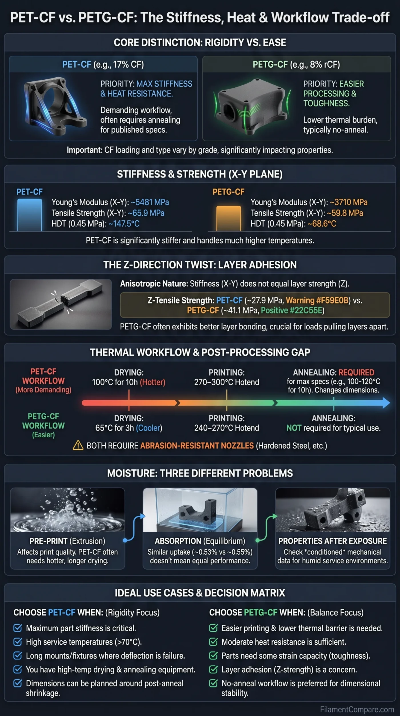
PET-CF generally targets higher rigidity and better retention of shape at elevated temperatures, while PETG-CF usually reaches useful carbon-fiber-reinforced performance with a less demanding thermal workflow. The choice is not simply PET versus PETG, because carbon-fiber loading, fiber type, print orientation and post-print annealing can materially change the result. For functional parts, the useful distinction is whether the priority is minimum deflection and higher heat capability or easier drying, lower hotend demand and fewer post-processing steps.
Where Each Option Makes Sense
Choose PET-CF when: part stiffness, resistance to flex under load and performance at higher service temperatures matter enough to justify a hotter drying and printing process. It is especially relevant to rigid mounts, fixtures, tooling and parts where geometry must remain stable under load.
Choose PETG-CF when: you want a stiff, dimensionally stable engineering filament without turning every part into a high-temperature post-processing job. It is usually the easier fit for functional prototypes, housings and brackets when moderate heat resistance is sufficient.
Do not choose from the material name alone. A high-fiber PET-CF and a lower-fiber PETG-CF are not a controlled test of PET versus PETG chemistry. The individual formulation can change stiffness, layer strength, drying requirements and heat behavior.
| Decision point | PET-CF17 example[a] | PETG-rCF08 example[b] |
|---|---|---|
| Polymer matrix | PET with carbon-fiber reinforcement | Glycol-modified PET with recycled carbon-fiber reinforcement |
| Carbon-fiber loading in this comparison | 17 wt% carbon fiber | 8 wt% recycled carbon fiber |
| Young’s modulus, X-Y | 5481.0 ± 223.7 MPa | 3710.1 ± 151.1 MPa |
| Tensile strength, X-Y | 65.9 ± 1.0 MPa | 59.8 ± 0.3 MPa |
| Tensile strength, Z | 27.9 ± 1.3 MPa | 41.1 ± 4.1 MPa |
| Elongation at break, X-Y | 2.4 ± 0.5% | 5.7 ± 1.0% |
| HDT at 0.45 MPa | 147.5°C | 68.6°C |
| Equilibrium water absorption at 23°C, 70% RH | 0.53% | 0.55% |
| Recommended nozzle temperature | 270–300°C | 240–270°C |
| Recommended build plate temperature | 70–80°C | 60–70°C |
| Chamber requirement in these TDS profiles | Room temperature | Room temperature |
| Drying recommendation | 100°C for 10 h | 65°C for 3 h |
| Cooling fan | Off | 0–50% |
| Annealing listed in TDS | 120°C for 10 h recommended for best performance | Not specified as required |
| Main practical trade-off | Higher stiffness and heat capability in this formulation, with a hotter and longer material-preparation workflow | Lower thermal burden and simpler post-print use, with lower stiffness and HDT in this formulation |
The table is not a pure PET-versus-PETG experiment. Polymaker identifies PET-CF17 as a 17 wt% carbon-fiber grade and PETG-rCF08 as an 8 wt% recycled-carbon-fiber grade.[d] Carbon-fiber content is therefore another variable. The PET-CF17 TDS also states that its reported mechanical specimens were annealed, while PETG-rCF08 is characterized without a listed annealing step. The useful comparison is between two complete material-and-workflow packages, not just two polymer acronyms.
Stiffness Gains Depend on Carbon Loading and Post-Processing
For a bracket, fixture or sensor mount that feels too flexible, Young’s modulus is often more informative than tensile strength. Tensile strength describes the stress reached before tensile failure; modulus describes how readily the part deforms while it is still operating within its elastic range. A material can therefore have only a moderate increase in tensile strength while producing a much stiffer-feeling part.
The same-brand data above illustrates that distinction. The separation between the two grades is much more pronounced in X-Y Young’s modulus than in X-Y tensile strength. For a long camera mount, measurement fixture or electronics bracket, that can matter because excessive movement may make the part unsuitable long before it actually breaks.
Where PET-CF’s Stiffness Is Useful
- Long brackets where tip deflection needs to stay low
- Jigs that must hold a repeatable position
- Camera, sensor and measurement mounts
- Fixtures loaded continuously rather than only during handling
- Parts exposed to both mechanical load and elevated temperature
Where PETG-CF May Be Stiff Enough
- Functional housings and covers
- Prototype brackets with shorter unsupported spans
- Machine accessories away from high-temperature zones
- Parts where some strain capacity is more useful than maximum rigidity
- Low-volume prototypes where post-processing time matters
Carbon-fiber percentage prevents a simple chemistry-based verdict. Comparing a 17% CF PET formulation with an 8% CF PETG formulation cannot reveal how two otherwise identical matrices would behave at identical fiber loading. Fiber length, dispersion, interface chemistry and other additives can also change the result. Grade-level data should take priority over a generic PET-CF or PETG-CF label.
Moisture Is Three Different Problems, Not One Number
Moisture claims around carbon-filled polyesters are easy to misread because spool condition, equilibrium water uptake and mechanical behavior after moisture exposure are different measurements. A filament can absorb relatively little water in service and still print more cleanly after drying. Conversely, two materials can reach similar equilibrium water content without retaining identical mechanical properties after conditioning.
1. Moisture Before Printing
This affects extrusion behavior. Water in the filament can contribute to inconsistent flow, rougher extrusion, stringing or other print defects. Drying recommendations therefore describe preparation of the spool rather than outdoor durability of the finished part.
2. Water Absorbed by the Printed Part
Equilibrium water absorption describes how much moisture the specimen takes up under a defined conditioning environment. In the Polymaker example, PET-CF17 and PETG-rCF08 end up remarkably close despite having very different drying recommendations.
3. Properties After Moisture Exposure
The engineering question is how stiffness, strength and dimensions change after conditioning. Water-absorption percentage alone cannot provide that answer; conditioned mechanical data are needed.
This distinction explains an apparent contradiction in PET-CF. A grade can be marketed around low moisture sensitivity yet still have a pre-print drying recommendation. In the benchmark above, PET-CF17 calls for a much hotter and longer drying cycle than PETG-rCF08 even though the equilibrium absorption values reported under the same humidity condition are almost identical.
Do not convert water absorption directly into a wet-stiffness score. The PET-CF17 and PETG-rCF08 documents used here publish equilibrium absorption data, but they do not provide a corresponding wet Young’s modulus for these two grades. A 0.53% versus 0.55% absorption result does not prove that both printed parts retain stiffness equally after moisture conditioning.
For a humid enclosure, pump mount or part used near condensation, the better selection method is therefore: check the grade’s drying requirement for print quality, then look separately for conditioned mechanical data relevant to the service environment. If those data are unavailable, the material name by itself is not enough to quantify long-term wet performance.
Print Difficulty Is Mostly a Thermal Workflow Difference
The interesting result in this comparison is that an enclosure is not the main divider. Both Polymaker grades list room-temperature chamber conditions. The larger equipment gap appears before and after extrusion: dryer capability, hotend temperature and annealing.
PET-CF Workflow
- Dry: the reference TDS calls for a 100°C drying cycle.
- Print: the hotend must comfortably reach the upper 200°C range specified for the grade.
- Nozzle: a wear-resistant nozzle is the appropriate hardware class for the abrasive CF formulation.
- Chamber: this particular PET-CF does not require a heated chamber.
- Post-process: maximum published performance is tied to an annealing workflow.
PETG-CF Workflow
- Dry: the reference grade uses a substantially lower drying temperature and shorter cycle.
- Print: its nozzle range starts lower and fits more all-metal desktop hotends.
- Nozzle: carbon fiber still makes nozzle wear a hardware consideration.
- Chamber: the reference profile also runs at room chamber temperature.
- Post-process: the grade is intended to be used without a required annealing stage.
Carbon fiber changes the nozzle requirement on both sides. PETG-CF should not be treated as ordinary PETG simply because its temperature range is easier to reach. Abrasive reinforcement can wear a standard brass nozzle, while wear-resistant hardened-steel, ruby or equivalent abrasion-resistant nozzles are commonly specified for these grades.
This changes what “easier to print” means. PETG-CF can still require dry storage, a capable hotend and an abrasion-resistant nozzle, but its thermal preparation is usually less demanding in this comparison. PET-CF adds another practical threshold: a filament dryer capable of true high-temperature operation and, when the published performance depends on it, controlled annealing equipment.
Annealing Turns PET-CF Into a Different Kind of Commitment
Annealing is not a small footnote when the mechanical data themselves come from annealed specimens. The PET-CF17 TDS states that all reported specimens were annealed. That means a freshly printed part should not automatically be expected to reproduce every modulus, strength or HDT number shown in the sheet.
It also changes dimensional planning. The PET-CF17 shrinkage test records further dimensional change after the annealing stage rather than a perfectly unchanged printed geometry. For a simple mounting plate this may be manageable; for a bearing bore, locating pin, press-fit feature or closely spaced fastener pattern, post-anneal dimensions can be more important than the nominal CAD dimensions.
Loose-Tolerance Fixture
Annealing is easier to accommodate when the part has clearance holes, broad contact surfaces and no precision mating feature.
Precision Bore or Press Fit
Plan the final tolerance around the post-anneal part. Reaming, drilling or machining after thermal treatment may be more predictable than relying on the as-printed dimension.
Thin or Unsupported Geometry
Annealing can add deformation risk. Thin walls, bridges and large overhangs deserve more attention than a thick, well-supported block.
There is also a current documentation detail worth checking before processing a finished PET-CF17 part. The technical data sheet lists 120°C for 10 hours, while the current PET-CF17 product-page FAQ states 100°C for 10 hours.[c] When official documents disagree, use the instructions supplied for the exact material revision, spool and current printer profile rather than treating one comparison-page value as universal.
Fair comparison rule: an annealed PET-CF result should not be presented as though it were automatically equivalent to an as-printed PET-CF result. If two grades are being ranked for a production part, compare them in the condition in which the parts will actually be used.
Z-Direction Strength Can Reverse the Simple PET-CF Ranking
A stiffness chart viewed only in the X-Y plane can give the impression that PET-CF wins every structural category. The same dataset shows why that assumption fails. PET-CF17 has the higher X-Y tensile strength and much higher X-Y modulus in this comparison, yet PETG-rCF08 records the higher Z-direction tensile strength.
That matters because printed parts are anisotropic. A vertical mounting tab, snap feature or bolt-loaded wall may place more stress across layer interfaces than along roads deposited in the X-Y plane. The highest modulus on the datasheet is not automatically the relevant number for the failure direction in the part.
Design implication: if the expected load pulls layers apart, check Z tensile or Z flexural data before choosing a filament from its X-Y stiffness. If the load mainly bends a long member within the printed plane, X-Y modulus may be the more useful screening property.
Higher carbon-fiber loading can improve rigidity without removing the layer-interface problem created by the printing process. Part orientation, wall layout, raster direction, temperature, cooling and the individual formulation still determine how much of the material’s in-plane capability reaches the finished component.
Choosing by Part Requirement
| Part requirement | Better fit | Why | Condition to check |
|---|---|---|---|
| Rigid inspection jig | PET-CF | Higher modulus is useful when small deflections affect repeatability. | Verify whether published performance assumes annealing. |
| Long camera or sensor mount | PET-CF | Lower elastic deflection is often more valuable than extra strain capacity. | Orient the part so the critical load does not rely unnecessarily on weak Z interfaces. |
| General functional prototype | PETG-CF | Lower drying and printing temperatures reduce preparation burden. | Confirm that the expected service temperature stays within the selected grade’s limits. |
| Tight-tolerance part with no post-processing | PETG-CF | A no-anneal workflow removes one source of post-print dimensional movement. | Dimensional accuracy still depends on printer calibration and formulation. |
| Part close to a sustained heat source | PET-CF | The PET-CF benchmark has a much higher HDT after its specified processing. | Use service-temperature data for the actual grade and specimen condition. |
| Part heavily loaded across layer lines | Grade-specific | The example PETG-CF has higher Z tensile strength despite lower X-Y stiffness. | Check Z data rather than assuming the stiffer material also has stronger layer-direction performance. |
| Open-printer workflow | Either can work | Both reference grades list room-temperature chamber conditions. | Hotend and dryer capability may still eliminate PET-CF on some machines. |
| Humid service environment | Grade-specific | Similar equilibrium absorption does not prove equal wet-property retention. | Look for conditioned mechanical data if moisture exposure affects the design. |
| Part needing some strain before failure | PETG-CF tendency | The reference PETG-CF shows greater X-Y elongation at break. | Do not treat elongation as a substitute for impact or fatigue data. |
Where the Decision Lands
Choose PET-CF when the part is limited by flex, heat exposure or dimensional movement under sustained mechanical load and you have the equipment to dry, print and, where specified, anneal the selected grade correctly.
Choose PETG-CF when you want carbon-fiber-reinforced stiffness and a technical surface with a lower thermal barrier to printing and no planned annealing stage.
Either option can work when the part is a moderate-load indoor fixture, enclosure or bracket and the geometry provides enough stiffness without relying on the material’s maximum published properties.
Neither material label solves weak orientation, insufficient wall thickness, poor interlayer bonding or a design whose service temperature exceeds the tested condition of the grade.
Check the exact datasheet first when moisture exposure, tight tolerances, Z-direction loading or annealing affects the part. Carbon-fiber percentage and specimen conditioning can change the ranking enough that a generic PET-CF-versus-PETG-CF rule becomes misleading.
Technical Sources and Documentation
- [a] TDS_FIBERON PET-CF17_V1.0_EN (Used for PET-CF17 mechanical, thermal, moisture, printing, drying, annealing and dimensional-test values.)
- [b] TDS_FIBERON PETG-rCF08_V1.0_EN (Used for PETG-rCF08 mechanical, thermal, moisture, printing and drying values.)
- [c] PET-CF17 – Fiberon 3D Printing Filament by Polymaker (Used to verify the current product-page annealing guidance and nozzle recommendation context.)
- [d] PETG-rCF08 – Fiberon 3D Printing Filament by Polymaker (Used for the published 8 wt% recycled-CF versus 17 wt% CF formulation distinction and product-level workflow information.)
