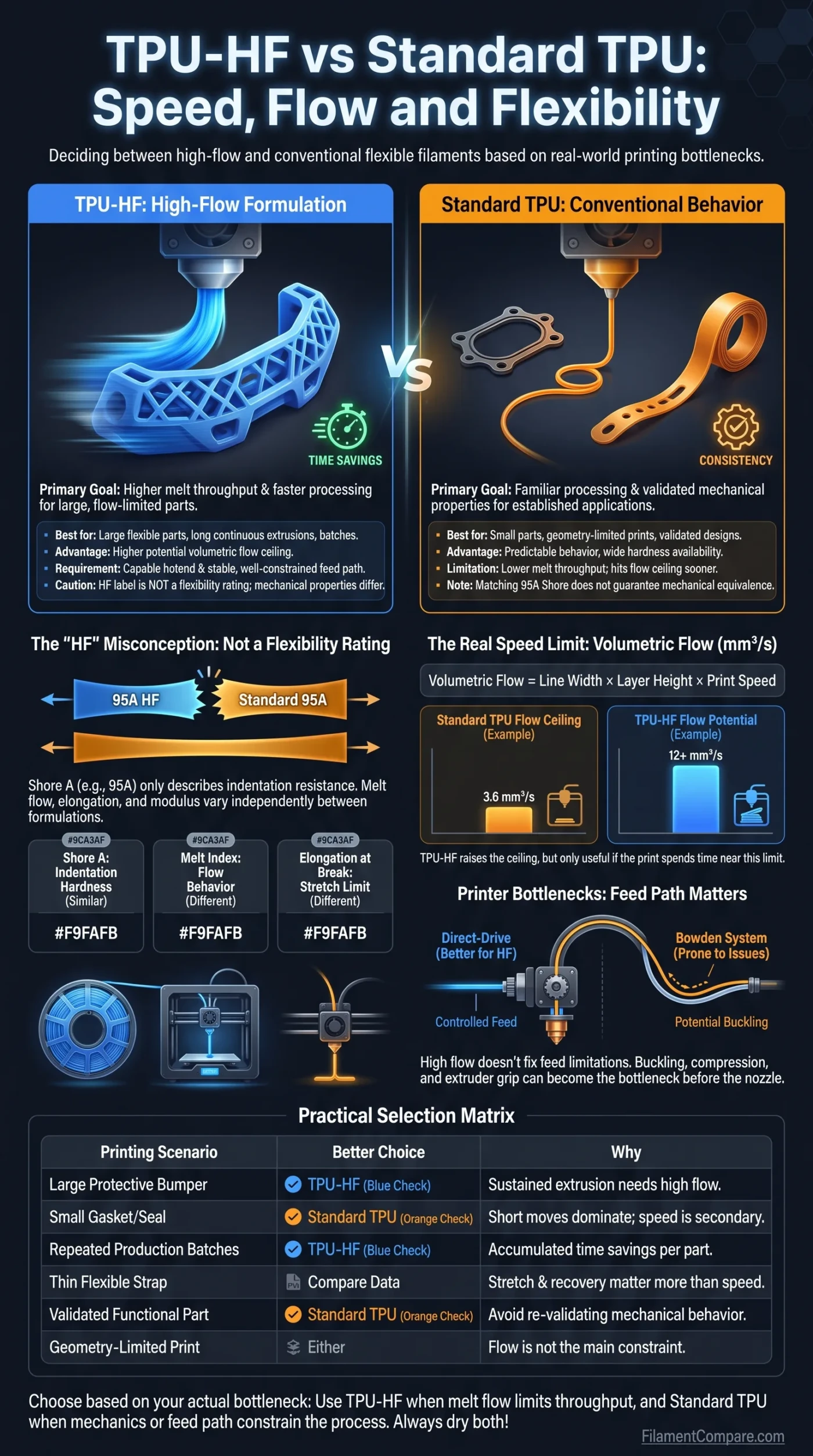
TPU-HF is formulated to move molten material through the hotend at a higher rate than conventional TPU, while standard TPU prioritizes the familiar processing and mechanical behavior of its particular grade. The practical choice is therefore not simply “fast TPU versus slow TPU”: it depends on whether melt flow is actually limiting the print, whether the extruder can feed flexible filament at the required rate, and whether the finished part must match a specific stretch and recovery behavior.
What the Choice Changes
Choose TPU-HF when throughput is the bottleneck: large flexible parts, repeated production runs, thick walls and long continuous extrusion paths give a high-flow formulation room to save time.
Choose standard TPU when speed is secondary: small parts, geometry-limited prints or applications already validated around a particular TPU grade may gain little from changing material.
Do not treat the HF label as a flexibility rating. A 95A TPU-HF and a standard 95A TPU can share the same nominal Shore hardness while differing in melt behavior, elongation, modulus and other formulation-dependent properties.
| Decision Point | TPU-HF | Standard TPU |
|---|---|---|
| Primary formulation goal | Higher melt throughput and faster processing | Conventional flexible-filament processing behavior |
| Maximum usable volumetric flow | Usually higher, but strongly grade- and hotend-dependent | Usually lower for a comparable hardness class |
| Potential print-speed advantage | Largest on long, flow-limited extrusion moves | More likely to hit its flow ceiling sooner |
| Small-part time saving | Can be modest when acceleration and feature speed dominate | May finish in a similar time when flow is not the limiting factor |
| Shore hardness | HF does not define hardness; 95A HF products are only one example | Available across different hardness grades and formulations |
| Mechanical equivalence | Not guaranteed by matching the Shore rating | Depends on the exact formulation and printed geometry |
| Flexible-filament feeding | Higher flow does not remove buckling, compression or feed-path limitations | Feed-path control remains important, especially as softness increases |
| Retraction and pressure tuning | May need a profile matched to its faster pressure response and higher throughput | Often run at lower flow, but still needs TPU-specific tuning |
| Moisture sensitivity | Still moisture-sensitive; HF does not remove drying requirements | Also moisture-sensitive and can print inconsistently when wet |
| Best workload | Large flexible parts, batches and throughput-focused printing | Smaller jobs, established profiles and applications tied to a known grade |
| Main limitation | The printer or geometry may prevent the material from reaching its higher flow potential | Lower melt throughput can become the dominant speed limit |
HF Changes Melt Behavior, Not the Meaning of 95A
“HF” normally describes a high-flow formulation. It should not be read as a separate TPU hardness class. Shore A describes resistance to indentation; melt flow describes how the polymer behaves while being processed in a molten state. Two properties can therefore move independently.
A useful same-manufacturer example is Polymaker’s PolyFlex TPU95-HF. Its current technical data lists a melt index of 9.3 g/10 min at 185°C under a 1.2 kg load and an X-Y elongation at break of 495.8 ± 16.2%.[b] Standard PolyFlex TPU95 is listed at 3–6 g/10 min at 210°C under the same nominal load and 551.2 ± 23.5% X-Y elongation at break.[c]
Do not calculate an “HF flow multiplier” from those melt-index values. The test temperatures are different. Melt index is meaningful only with its test method, temperature and applied load attached, so 9.3 versus 3–6 cannot be treated as a controlled ratio between the two filaments.
The mechanical data also illustrates why matching 95A labels do not establish mechanical equivalence. Shore hardness does not tell you how far a specimen stretches before failure, how much force is needed at a given strain, how quickly it recovers after deformation or how a printed wall behaves under bending.
Shore A Hardness
Describes indentation hardness. Useful for separating softer and harder TPU grades, but not a complete measure of flexibility.
Stress and Modulus
Describe resistance to deformation under load. Two materials with the same Shore rating can respond differently when stretched.
Elongation at Break
Describes how far a test specimen can extend before failure under the stated test method. It is not interchangeable with Shore hardness.
Volumetric Flow Sets the Speed Ceiling That Matters
Linear print speed in mm/s is only one part of the extrusion load. The hotend must supply enough molten polymer to fill the requested line width and layer height at that speed. That demand is better expressed as volumetric flow in mm³/s.
Flow Relationship
Volumetric flow = line width × layer height × print speed
A 0.42 mm line printed at a 0.20 mm layer height and 100 mm/s requests approximately 8.4 mm³/s. Changing only the speed to 150 mm/s raises the demand to approximately 12.6 mm³/s.
This is where TPU-HF can create a large difference. Bambu Lab’s TPU 95A HF comparison lists a maximum volumetric speed of 12 mm³/s for its HF material versus 3.6 mm³/s for the standard TPU used in that comparison, alongside example printing speeds of 147 mm/s and 44 mm/s respectively.[a] Those figures are manufacturer- and profile-specific examples, not universal limits for every high-flow or conventional TPU.
The distinction also explains why a slicer setting of 150 or 200 mm/s does not prove that a TPU is being deposited at that speed. If the filament profile imposes a lower volumetric-flow limit, the slicer must reduce the effective extrusion speed wherever the requested flow exceeds that limit.
A 3× Flow Difference Does Not Mean a 3× Shorter Print
Higher flow only removes one bottleneck. Outer walls, small perimeters, overhangs, bridges, short segments, acceleration limits and minimum layer times can all prevent the printer from spending much of the job near maximum volumetric flow. A large solid bumper may expose the difference immediately; a small lattice part containing hundreds of short moves may not.
Useful way to interpret an HF claim: ask what percentage of the model is flow-limited. The more time the print spends requesting extrusion near the standard TPU’s flow ceiling, the more opportunity TPU-HF has to reduce print time.
The Feed Path Can Become the Bottleneck Before the Nozzle
A high-flow formulation can move through the molten section more easily, but the filament is still flexible before it reaches the hotend. Drive gears must push a compressible strand through the filament path without letting it bend sideways, buckle, slip or accumulate excessive compression.
This distinction matters because an HF material can have enough melt capacity for a higher extrusion rate while the printer itself cannot feed it consistently at that rate. UltiMaker’s current TPU printing guidance specifically notes that flexible TPU is prone to buckling in Bowden-style systems and that a direct-drive arrangement provides greater control by shortening the path to the hotend.[d]
When TPU-HF Can Use Its Flow Advantage
- Well-constrained filament path
- Extruder suited to flexible filament
- Hotend capable of the requested melt rate
- Stable flow calibration
- Geometry containing sustained extrusion moves
Where the Printer Can Hold It Back
- Long or poorly constrained flexible-filament path
- Filament buckling between gears and hotend
- Excessive drive-gear pressure deforming the filament
- Retraction settings copied from rigid materials
- Hotend capacity below the filament’s useful flow potential
Retraction deserves the same separation. HF does not turn TPU into PLA. Flexible filament stores part of an extrusion or retraction movement as compression and extension in the strand itself, so pressure response remains different from a rigid filament. A profile designed for one TPU grade should therefore be treated as a starting point rather than proof that another HF or standard TPU can use identical retraction and flow-dynamics settings.
Same 95A Does Not Mean the Printed Parts Will Flex the Same Way
The finished object’s flexibility comes from both material behavior and structural geometry. Shore hardness describes only part of the first half of that equation. Wall thickness, wall count, rib geometry, infill structure and the direction of loading can change the apparent stiffness of a printed TPU part enough to overwhelm a modest material difference.
This becomes important when replacing standard 95A TPU with 95A HF in an existing functional design. Matching the Shore number is useful, but it does not establish that a seal compresses by the same amount, a strap stretches by the same amount under load or a vibration isolator returns energy in the same way.
For a meaningful flexibility comparison: keep the STL, orientation, nozzle, layer height, extrusion width, wall count and infill structure unchanged. If the HF sample is printed with a different shell structure to exploit higher speed, the test is comparing both material and geometry rather than the filament formulations alone.
Print Speed Can Also Change the Mechanical Result
Even with identical geometry, comparing a slowly printed standard TPU sample with an aggressively printed HF sample introduces a process difference. Higher throughput changes how much material must be heated per second and can alter extrusion consistency or bead bonding if temperature, cooling and flow calibration are not appropriate for the new rate.
For that reason, two different tests answer two different questions. Printing both materials under the same controlled process is useful for comparing formulations. Printing each material at its own highest stable production setting is useful for comparing real workflow performance. Mixing the two approaches can produce a result that is difficult to interpret.
Moisture Can Erase the Expected Speed Advantage
TPU is moisture-sensitive, and high flow does not remove that limitation. Bambu Lab’s TPU printing documentation warns that absorbed moisture can produce stringing, bubbles and weaker layer adhesion, while its TPU 95A HF documentation specifies drying before use under stated conditions.[e]
This matters more in a speed comparison than it may first appear. An HF spool producing unstable extrusion because of moisture can require a lower flow limit, slower walls or additional cleanup. Meanwhile, a properly dried standard TPU can look more controlled despite its lower theoretical throughput.
Do not benchmark wet standard TPU against dry TPU-HF—or the reverse. Drying condition, nozzle, layer geometry and test model should be controlled before attributing a speed or surface-quality difference to the HF formulation.
A Fair HF-versus-Standard Test Sequence
- Condition both filaments according to their manufacturers’ instructions.
- Use the same printer, nozzle diameter and test geometry.
- Calibrate extrusion or flow ratio for each filament rather than assuming both require the same value.
- Find a suitable printing-temperature range for each grade.
- Determine the highest stable volumetric flow instead of increasing only the slicer’s linear speed.
- Print the same functional sample with matching wall count, infill and orientation.
- Record actual print time, visible extrusion defects and part mass.
- Compare bending, stretch or recovery only after confirming that both samples were printed consistently.
Where TPU-HF Actually Saves Time
The strongest case for TPU-HF is not a particular slicer speed. It is a model that repeatedly asks for more volumetric flow than standard TPU can supply while the printer, hotend and motion system still have unused capacity.
| Printing Scenario | Better Starting Point | Why | Main Condition |
|---|---|---|---|
| Large protective bumper | TPU-HF | Thick walls and sustained extrusion can use additional melt throughput | The extruder and hotend must feed the requested flow reliably |
| Large flexible housing | TPU-HF | Long wall and infill paths can spend more time near a flow ceiling | Geometry must not be dominated by slow overhangs or tiny features |
| Repeated production parts | TPU-HF | Small per-part reductions can accumulate across a batch | The HF profile should already be validated for repeatability |
| Small gasket | Either | Total print time may be controlled by short moves rather than flow | Select by mechanical behavior and print consistency |
| Thin flexible strap | Grade-dependent | Stretch and recovery can matter more than maximum extrusion rate | Compare the mechanical data of the exact products |
| Vibration isolator | Grade-dependent | Part stiffness and deformation behavior dominate the decision | Test the finished geometry under its actual loading direction |
| Tiny detailed TPU component | Either | Acceleration, corners and feature-specific speed limits can reduce the HF advantage | Check the sliced time before changing material solely for speed |
| Existing validated functional part | Standard TPU may be simpler | Changing formulation can change mechanical response and requires revalidation | Switch when the expected throughput benefit justifies new testing |
Choosing by the Bottleneck You Actually Have
Practical Selection Matrix
- Choose TPU-HF when conventional TPU is hitting its stable volumetric-flow ceiling on large or repeated prints and the printer can reliably feed flexible filament at a higher rate.
- Choose standard TPU when the model is small, the existing profile is already reliable, or the required mechanical behavior has been validated around a specific conventional grade.
- Either option can work when the model spends little time near its flow limit. In that case, slicer restrictions, geometry and motion limits can make the theoretical throughput difference much less important.
- Compare exact datasheets when stretch, compression, recovery or load response matters. Matching Shore A ratings are not enough to declare the materials mechanically interchangeable.
- Check the printer before blaming the filament when higher commanded speed creates slipping, buckling or inconsistent extrusion. HF improves melt-flow capability; it does not remove flexible-filament feed limitations.
The most useful dividing line is therefore flow-limited versus non-flow-limited printing. TPU-HF has a clear purpose when the standard material cannot move enough polymer through the nozzle to use the printer’s available speed. When the model, feed path or required mechanical response is the real constraint, the HF label alone provides much less reason to switch.
Technical Sources and Documentation
- [a] Bambu Lab — TPU 95A HF (Used for the manufacturer comparison of maximum volumetric speed and example printing speed.)
- [b] Polymaker — PolyFlex™ TPU95-HF Technical Data Sheet (Used for TPU95-HF melt-index and elongation-at-break data.)
- [c] Polymaker — PolyFlex™ TPU95 Technical Data Sheet (Used for standard TPU95 melt-index and elongation-at-break data.)
- [d] UltiMaker — Printing with TPU: Best Practices for Flexible Success (Used for flexible-filament feeding and direct-drive versus Bowden context.)
- [e] Bambu Lab — TPU Printing Guide (Used for TPU moisture behavior and drying context.)
