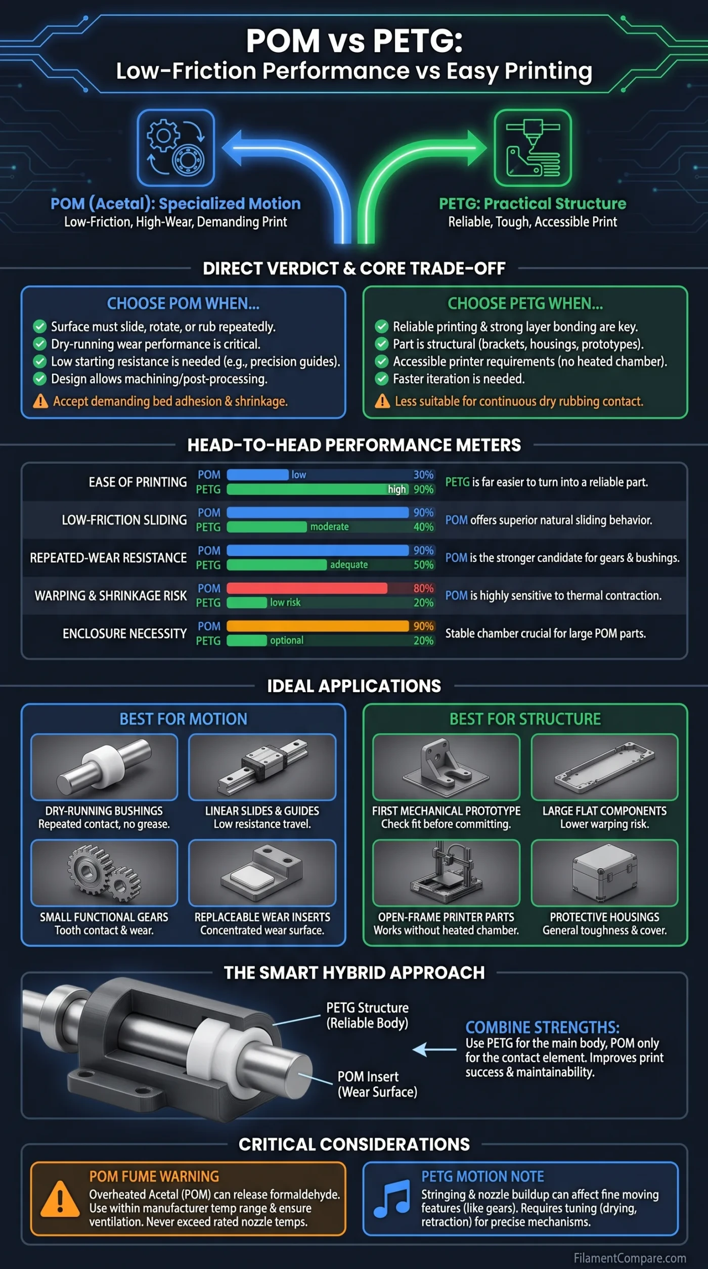
POM offers lower-friction sliding and stronger wear performance, while PETG is far easier to turn into a reliable FDM part. POM is the more specialized choice for bushings, guides, gears, and repeated dry motion; PETG is usually the more practical choice for prototypes, brackets, housings, and lightly moving components. The better filament depends on whether the harder problem is printing the part successfully or keeping it moving smoothly over time.
Direct Material Verdict
Choose POM when the printed surface will slide, rotate, or rub repeatedly against a shaft, rail, gear tooth, or another mechanical surface. Its low-friction and wear characteristics are the main reason to accept its demanding bed adhesion and shrinkage behavior.
Choose PETG when reliable printing, strong layer bonding, accessible printer requirements, and repeatable production matter more than dry-running wear performance. It is the safer starting point for prototypes and mechanisms with low loads or limited movement.
Use both when possible: a PETG structure with a small, replaceable POM bushing or wear pad often gives a better production workflow than printing the entire assembly from POM.
Dry-Running Bushings
POM
Better suited to repeated shaft contact where grease is unavailable or undesirable.
Linear Slides and Guides
POM
Lower sliding resistance and better wear behavior make it the stronger candidate for repeated travel.
Small Functional Gears
POM
Useful where tooth contact, noise, and progressive wear matter more than printing convenience.
First Mechanical Prototype
PETG
Faster to tune, easier to reprint, and better suited to checking fit before committing to POM.
Large Flat Components
PETG
Lower warping risk makes long rails, plates, and housings easier to produce accurately.
Open-Frame Printers
PETG
It normally prints without a heated chamber and works on widely available build surfaces.
Replaceable Wear Inserts
POM
A small POM insert can provide the sliding surface while the main structure remains PETG.
Repeated Small-Batch Printing
PETG
More predictable adhesion and lower rejection rates help when several matching parts are required.
| Decision Area | POM | PETG | More Suitable Choice |
|---|---|---|---|
| Polymer family | Polyoxymethylene or acetal; homopolymer and copolymer grades exist | Glycol-modified polyester; properties vary by formulation | Application-dependent |
| Primary reason to use it | Low-friction motion, wear resistance, stiffness, and low moisture uptake | Accessible printing, toughness, layer bonding, and general functional use | Application-dependent |
| Print difficulty | High; tuning-sensitive | Low to moderate | PETG |
| Typical nozzle range | Often about 210–240°C, but the spool specification must take priority[a] | Commonly around 230–260°C, depending on the grade and manufacturer | Grade-dependent |
| Typical bed range | Often about 100–130°C; many desktop beds cannot maintain this evenly | Usually about 70–90°C | PETG |
| Enclosure need | Strongly preferred; a temperature-stable chamber improves the chance of success | Usually optional for standard grades | PETG |
| Build plate behavior | Reluctant adhesion on many conventional surfaces; cellulose-based or product-specific solutions may be required | Usually reliable, although smooth PEI may need a release layer | PETG |
| Warping and shrinkage | High enough to affect long parts, flatness, holes, and bearing alignment | Usually limited under suitable settings | PETG |
| Layer-bond reliability | More dependent on chamber temperature, cooling rate, and extrusion tuning | Usually strong and repeatable | PETG |
| Natural sliding behavior | Very good for an unfilled thermoplastic; grade and counterface still matter | Moderate; a smooth print may still create noticeable drag | POM |
| Wear under repeated motion | Usually the stronger candidate for bushings, slides, and gear contact | Adequate for light duty, limited cycles, or replaceable prototypes | POM |
| Moisture behavior | Low moisture absorption compared with many engineering polymers | Can absorb enough moisture to worsen stringing, bubbling, and surface consistency | POM |
| Dimensional behavior after printing | The polymer is dimensionally stable in service, but FDM shrinkage can make the initial part difficult to control | Easier to print close to the intended form, though sustained load can alter fits over time | Depends on stage |
| Surface appearance | Dense, smooth-looking, and engineering-oriented when printed correctly | Often glossy; stringing and nozzle buildup can affect fine moving features | Geometry-dependent |
| Typical moving uses | Bushings, guide blocks, sliding pads, low-load gears, rollers, and latches | Adjustment knobs, temporary gears, hinges, fixtures, guards, and low-cycle sliders | Duty-dependent |
| Main limitation | Producing a flat, bonded, accurately sized part can require specialized hardware and repeated tuning | Higher sliding resistance and less favorable long-cycle wear in direct rubbing contact | Different limitations |
| Better overall choice | For repeated low-friction motion | For reliable general-purpose printing | No universal winner |
The POM and PETG ranges shown here combine manufacturer datasheets and established material guidance; they describe broad behavior rather than fixed results because brand, color, additives, moisture, geometry, orientation, and print settings can change the finished part.
Material Profiles for Moving Parts
POM Motion Profile
- Polymer type: Semi-crystalline polyoxymethylene, also called acetal
- Print difficulty: High
- Nozzle range: Product-dependent; one commercial POM-C filament specifies 210–240°C
- Bed range: Often 100–130°C for demanding POM filament grades
- Enclosure: Strongly preferred
- Drying need: Usually lower than nylon, but clean and dry storage still supports stable extrusion
- Typical behavior: Stiff, low-friction, wear-resistant, low moisture uptake, and sensitive to thermal contraction during printing
- Best uses: Bushings, sliding guides, wear pads, small gears, rollers, and repeated mechanical motion
PETG Production Profile
- Polymer type: Glycol-modified polyester
- Print difficulty: Low to moderate
- Nozzle range: Usually around 230–260°C, depending on formulation
- Bed range: Usually around 70–90°C
- Enclosure: Normally optional for standard PETG
- Drying need: Helpful when stringing, popping, rough extrusion, or weak surface consistency appears
- Typical behavior: Tough, slightly compliant, strongly bonded between layers, and prone to stringing if flow and temperature are not controlled
- Best uses: Brackets, enclosures, fixtures, prototypes, low-cycle mechanisms, and the structural body of hybrid assemblies
Relative Performance in FDM Use
Ease of Printing
Low-Friction Sliding
Repeated-Wear Performance
Desktop Print Repeatability
Dry-Running Suitability
Large-Part Printability
These meters are relative indicators for printed-part selection rather than laboratory grades. Filament formulation, pigment, additives, moisture, print orientation, surface finish, counterface material, load, and slicer settings can move the practical result in either direction.
Low Friction Is Not the Same as a Glossy Surface
A PETG print can look smooth and still resist motion more than a visually less polished POM part. Surface roughness affects friction, but it is only one part of the contact system. The polymer’s sliding behavior, surface energy, deformation under load, contact pressure, heat buildup, and the material rubbing against it all contribute to the result.
POM is used for gears and other moving components because acetal combines low friction with wear resistance, stiffness, and dimensional stability in service[b]. That does not mean every printed POM surface will slide perfectly. A warped bore, visible seam, over-extruded wall, or rough layer transition can create more drag than a well-printed PETG prototype.
Starting Friction and Running Friction
A mechanism may resist its first movement and then travel more freely once motion begins. This difference matters in adjustment screws, camera sliders, small actuators, latches, and precision guides. A material that produces irregular stick-and-release movement can cause vibration, noise, or poor positioning even when the average force appears acceptable.
POM is generally better suited to controlled sliding because it is less likely to grip the counterface as strongly as PETG. PETG can still work where movement is slow, occasional, manually driven, or supported by generous clearance. The decision changes when the part must start smoothly thousands of times.
POM’s Printing Contradiction
The low surface interaction that makes POM useful in motion also contributes to difficult build plate adhesion. A POM filament may resist common print surfaces, contract strongly while cooling, and pull its corners inward or upward. Long guide blocks, flat wear strips, and wide gears are especially vulnerable because a small shape error can alter contact across the entire mechanism.
A commercial POM-C filament datasheet lists a 210–240°C nozzle range and a 100–130°C bed range, with 230°C and 130°C used as reference settings[c]. These values are not universal. They show why a printer that handles PETG comfortably may still be unsuitable for POM: the bed may not reach the required temperature, the magnetic sheet may lose holding strength, or the chamber may remain too cool.
Build Plate Contact
Many POM printing instructions recommend a product-specific adhesive or a cellulose-based contact surface. The goal is not merely to create a sticky first layer. The attachment must remain stable while the upper layers cool and contract. A brim can add contact area, but it cannot fully compensate for an unsuitable surface or a large temperature gradient.
Chamber Stability
A closed printer reduces abrupt cooling around the part. This can improve layer bonding and lower the force pulling the print away from the bed. A basic enclosure may still be insufficient for a long POM component when the internal air remains cool or changes each time the room door opens. Chamber temperature, bed uniformity, part geometry, and cooling rate work together.
POM temperature control requires restraint. Use the filament manufacturer’s range, avoid leaving POM stationary in a hot nozzle, and ventilate the printing area. Overheated acetal can release formaldehyde-containing decomposition products, so raising nozzle temperature without a verified reason is not an appropriate response to weak bonding[d].
Bushings, Slides, and Gears Under Repeated Motion
Bushings on Metal Shafts
A bushing must do more than fit over a shaft on the day it is assembled. It must preserve a usable running clearance after repeated movement. Too little clearance causes binding when the bore is slightly oval or when the assembly warms. Too much clearance creates play, noise, and inaccurate positioning.
POM is the more natural choice for a dry-running bushing because it offers favorable sliding and wear properties with low moisture absorption[e]. PETG can serve as a temporary bushing for load testing, alignment checks, or a low-cycle fixture. It is less convincing when the bushing is expected to operate continuously against a metal shaft.
Linear Guides and Sliding Blocks
Linear motion exposes errors that may be hidden in a rotating part. A guide can bind at one end if it is bowed by only a small amount. For this reason, POM’s wear advantage does not automatically make it the better printed guide. The part must first be straight, parallel, and dimensionally usable.
PETG is often the better prototype material for developing rail clearance and mounting geometry. Once the fit has been tested, the sliding element can be redesigned as a shorter POM pad or insert. This reduces the length of the POM print and makes contraction easier to manage.
Small Gears
POM is widely associated with gears because low friction and wear resistance help at the tooth interface. FDM gear performance, however, also depends on tooth accuracy, layer orientation, root shape, backlash, seam location, and shaft alignment. A visibly distorted POM gear is not improved by the polymer’s datasheet reputation.
PETG is useful for confirming gear diameter, center distance, tooth count, and assembly clearance. It can remain in service in a slow, lightly loaded mechanism. For regular operation, POM becomes more attractive when the printer can produce consistent teeth and the load remains within the limits of the printed geometry.
Dimensional Accuracy Before and After Assembly
POM and PETG create two different dimensional questions. With POM, the first concern is whether thermal contraction and bed lift will allow the part to reach the intended shape. With PETG, the first print is normally easier to control, but a tightly loaded surface may change through creep or gradual deformation.
Why Printed Bores Run Tight
- Internal perimeters can place material slightly inside the nominal CAD diameter.
- A seam can form a local ridge that catches the shaft.
- Horizontal holes can sag along their upper surface.
- Uneven shrinkage can turn a round bore into an oval.
- Layer lines can create directional resistance along the shaft.
- Excess flow can reduce both hole diameter and designed running clearance.
Critical POM bores should not rely on a nominal CAD diameter alone. A test coupon using the same wall count, orientation, layer height, and print environment is more useful. For accurate bushings, leaving machining allowance for drilling or reaming can produce a more dependable shaft fit than repeated slicer compensation.
Material Stability Does Not Guarantee Print Accuracy
POM has low moisture uptake and good dimensional stability as an engineering polymer, yet FDM processing can still leave residual stress, curvature, or shrinkage error. PETG has less favorable sliding behavior but can produce a straighter and more repeatable part on an ordinary printer. The preferred material must therefore be evaluated at two stages: after printing and after extended use.
Why PETG Often Wins the Production Stage
PETG does not need to match POM’s sliding performance to be useful. Its main advantage is that a working part can usually be produced with less printer modification, fewer failed attempts, and better consistency across several copies. Standard PETG commonly prints on heated beds around 80–90°C and does not normally require a heated chamber.
A Prusament PETG technical sheet, for example, specifies 230 ± 10°C at the nozzle and 80 ± 10°C at the bed for one PETG formulation[f]. Another PETG formulation may require a different range, but the printer demands are still generally more accessible than those of POM filament.
PETG Defects Matter More on Moving Features
Stringing is often cosmetic on a housing, but it can interfere with a narrow guide channel or a fine gear tooth. Nozzle buildup can leave small deposits on bearing surfaces. Excessive temperature may soften details, while too much cooling may reduce layer bonding. Prusa’s PETG guidance identifies stringing, bridging, and overhang behavior as areas that require attention[g].
These issues are usually manageable through drying, temperature control, retraction tuning, travel planning, and a clean nozzle. That makes PETG a productive material for mechanism development even when it is not the preferred final sliding surface.
A PETG Body with POM Wear Components
Printing the entire assembly from one material is not always the most efficient design. A large housing may gain little from POM, while a small contact pad inside it may gain a great deal. Separating structural and sliding functions allows each polymer to be used where its behavior matters.
PETG Structure
Use PETG for the body, mounting flange, cover, alignment frame, handle, or other geometry that benefits from reliable printing and strong layers.
POM Contact Element
Use POM for the bushing, rail pad, roller, gear, thrust surface, latch contact, or other small part exposed to motion.
Mechanical Retention
Capture the POM insert with a shoulder, screw, clip, dovetail, or enclosed pocket rather than assuming strong adhesive bonding to its low-energy surface.
This layout also improves maintenance. A worn insert can be replaced without discarding the whole PETG assembly. It also limits the amount of POM that must be printed, reducing exposure to large flat surfaces and long contraction paths.
Can Lubricated PETG Replace POM?
Lubrication can lower the starting resistance of a PETG slider or bushing, but it does not change PETG into a naturally low-friction bearing polymer. The result depends on lubricant compatibility, pressure, speed, temperature, dust exposure, and whether the lubricant remains in the contact zone.
For a manually operated adjustment that moves a few times each month, a compatible lubricant and replaceable PETG part may be sufficient. For continuous dry motion, a clean mechanism, or a device that cannot be serviced regularly, POM remains the more suitable candidate.
Do not select a grease by general plastic compatibility alone. Check compatibility with the exact PETG or POM grade, nearby elastomers, seals, coatings, and the service temperature. Dust-catching lubricants can make an exposed rail less predictable over time.
A Practical Wear Test for the Actual Part
A single friction coefficient taken from a resin datasheet cannot describe every printed mechanism. The value changes with load, speed, counterface material, surface roughness, lubrication, temperature, print orientation, and polymer grade. A controlled part-level test is more useful when the mechanism will see many cycles.
Prepare Matching Samples
- Use the same CAD geometry and designed clearance.
- Keep wall count, layer height, nozzle diameter, and orientation consistent.
- Use the same shaft, rail, or mating surface.
- Apply the same radial or normal load.
- Keep travel distance, speed, and environmental conditions consistent.
- Record the initial dimensions before assembly.
Measure More Than Initial Smoothness
- Force required to start motion
- Force required to maintain motion
- Clearance after 100, 1,000, and 10,000 cycles
- Change in bore diameter or guide width
- Visible scoring, polishing, flattening, or material transfer
- Plastic dust around the contact zone
- Noise and irregular stick-release movement
- Temperature rise near the contact surface
The test should be treated as an application check, not a universal material ranking. A result obtained from one filament brand, one shaft finish, and one load only applies directly to that setup (or to a closely matched design).
Where Each Material Fits in Real Parts
| Part or Use Case | More Suitable Material | Reason | When the Other Material Can Work |
|---|---|---|---|
| Dry bushing on a metal shaft | POM | Lower friction and better wear behavior under repeated sliding | PETG for fit testing, low load, or a short service life |
| Precision linear guide block | POM, after geometry validation | Better sliding behavior once a straight and accurate part is achieved | PETG for developing rail clearance and mounting geometry |
| Small low-speed gear | POM | More favorable tooth-contact wear and friction | PETG for a temporary gear or lightly loaded manual drive |
| Large machine bracket | PETG | The part gains little from low friction and benefits from reliable production | POM only when a contact surface is integrated into the bracket |
| Protective housing | PETG | Easier printing, strong layers, and lower warping risk | POM rarely provides enough extra value for the full housing |
| Adjustment slider used occasionally | PETG | Limited motion may not justify POM’s printing demands | POM when smooth starting force and long cycle life matter |
| Replaceable rail pad | POM | Small geometry limits print risk and concentrates POM at the wear surface | PETG for a disposable or lightly used pad |
| Assembly and clearance prototype | PETG | Fast reprinting makes dimensional iteration easier | POM for the final validation after the design is stable |
| Repeated latch contact | POM | Favorable fatigue, sliding, and wear behavior for repeated engagement | PETG when the latch is used infrequently and has broad tolerances |
| Hand-operated knob and shaft collar | PETG | General toughness and printability matter more than bearing performance | POM where the collar also acts as a low-friction thrust surface |
| Open-frame-printer mechanism | PETG | Much easier to produce without a controlled chamber | POM only for small parts when bed and adhesion requirements can be met |
| PETG frame with separate bushing | Hybrid | Combines accessible structural printing with a dedicated wear surface | A single material may be simpler for non-critical motion |
Printing Failures and Service Failures Are Different
| Observed Problem | Likely POM Cause | Likely PETG Cause | First Check |
|---|---|---|---|
| Part releases from the bed | Unsuitable surface, inadequate bed temperature, or strong contraction | Contaminated sheet or incorrect first-layer height | Surface preparation and first-layer contact |
| Corners lift | Thermal gradient, long contraction path, or cool chamber | Low bed temperature, aggressive cooling, or thin contact area | Bed uniformity, chamber airflow, and geometry |
| Bushing does not fit the shaft | Shrinkage, ovality, seam ridge, or excess flow | Excess flow, small CAD clearance, or horizontal-hole sag | Measure the bore in several directions |
| Slider moves unevenly | Warped guide surface or rough layer transition | Higher surface drag, stringing, or localized deformation | Rail alignment and contact marks |
| Clearance grows with use | Weak printed surface, poor layer bonding, or unsuitable load | Wear, creep, heat buildup, or excessive contact pressure | Compare dimensions before and after cycling |
| Gear becomes noisy | Tooth distortion, eccentric bore, or rough seam placement | Tooth deformation, friction, or increasing backlash | Center distance, runout, and tooth contact pattern |
| Layers separate | Low chamber temperature, excessive cooling, or insufficient fusion | Low nozzle temperature, excessive cooling, or unsuitable orientation | Layer direction relative to operating load |
| Plastic dust appears | High load, rough counterface, misalignment, or unsuitable grade | Progressive rubbing wear or softened contact surface | Contact pressure and counterface finish |
Where POM and PETG Fit Better
Choose POM When
- The part slides, rotates, or rubs during normal operation.
- Dry-running performance is preferred.
- A bushing, wear pad, roller, or gear will see many cycles.
- Low starting resistance and smoother motion matter.
- Moisture-related dimensional change must remain low.
- The printer can provide the required bed temperature and enclosure stability.
- The design allows machining, reaming, or measured clearance adjustment.
POM Is Less Suitable When
- The printer has a low-temperature bed or an open build area.
- The part is large, flat, long, or difficult to hold on the bed.
- Several matching parts must be produced with minimal setup time.
- Low friction offers no practical benefit to the component.
- Ventilation and temperature monitoring cannot be provided.
Choose PETG When
- The part is a bracket, body, guard, mount, or prototype.
- Movement is occasional, low-load, or manually driven.
- Reliable printing matters more than minimum sliding resistance.
- An open-frame desktop printer will be used.
- The design is still being revised and may require several iterations.
- Strong layer bonding and moderate flexibility are useful.
- The wear element can be replaced or separated from the main body.
PETG Is Less Suitable When
- A surface runs continuously against a shaft or rail without lubrication.
- Progressive wear would cause unacceptable play.
- Stick-release motion would affect accuracy or noise.
- High contact pressure is concentrated on a small area.
- The component is expected to function as a long-life bearing material.
Material Selection Matrix
Best Choice by Priority
Choose POM if the part’s main job is motion. Bushings, sliding pads, guide elements, small gears, rollers, and repeated latch contacts are the applications where its low-friction and wear behavior can justify the extra printing effort.
Choose PETG if the part’s main job is structure. Brackets, housings, fixtures, adjustment parts, mechanism prototypes, and components with limited travel usually benefit more from predictable printing than from POM’s sliding properties.
Choose a hybrid layout if only one surface needs POM. A PETG body with a mechanically retained POM insert reduces failed-print risk, simplifies replacement, and places the specialized material directly at the contact point.
There is no overall winner. PETG makes production easier; POM makes repeated motion easier. The correct choice follows the part’s operating duty, not the material name alone.
Common POM and PETG Questions
Can PETG Be Used for a Bushing?
Yes, when the load is low, movement is occasional, clearance is generous, and the part can be replaced. POM is generally the better candidate for a dry-running bushing expected to complete many cycles.
Does Sanding PETG Give It POM-Like Friction?
Sanding can remove layer peaks and reduce local roughness, but it does not reproduce POM’s polymer-level sliding and wear behavior. It may improve a PETG prototype without making the materials equivalent.
Is POM Always More Dimensionally Accurate?
No. POM has good dimensional stability in service, but its FDM shrinkage and warping can make the initial printed shape harder to control. PETG often gives better desktop-print repeatability even though it is less suitable for long-term rubbing contact.
Can Grease Make a PETG Slider Equivalent to POM?
A compatible lubricant can reduce drag in a light-duty PETG mechanism. It does not remove differences in wear, creep, heat response, and long-term dimensional behavior. Lubrication also introduces maintenance and contamination concerns.
Should the Final Part Be Printed in POM Immediately?
Usually not when the design is untested. Printing the first versions in PETG allows faster correction of bore size, rail clearance, shaft spacing, and mounting geometry. POM can then be reserved for the verified wear component or final motion part.
Does Every POM Filament Use the Same Settings?
No. POM-H, POM-C, modified acetal grades, pigments, and manufacturer formulations can require different nozzle temperatures, bed surfaces, chamber conditions, and cooling strategies. The spool-specific technical sheet should override a general POM profile.
Technical References
- [a] Preliminary Technical Data Sheet Tarfuse POM (Used for the manufacturer-listed POM-C filament nozzle and heated-bed ranges. The document also identifies the material as a polyacetal copolymer intended for FFF processing.)
- [b] High-Performance POM Plastic Gear Material (Used for POM’s relationship to low friction, wear resistance, stiffness, and gear applications. Resin properties do not automatically equal the properties of an FDM part.)
- [c] Preliminary Technical Data Sheet Tarfuse POM (Used for the example reference settings of 230°C nozzle temperature and 130°C bed temperature. Other POM filament grades may specify different conditions.)
- [d] Acetron POM-H Natural Safety Data Sheet (Used for the overheating and formaldehyde-decomposition warning. This is a safety document rather than a mechanical-performance datasheet.)
- [e] POM Plastic – Polyoxymethylene (Used for general POM sliding, wear, moisture-absorption, and dimensional-stability behavior in engineering applications.)
- [f] Technical Datasheet: Prusament PETG V0 by Prusa Polymers (Used for one verified PETG formulation’s nozzle and bed settings. The same sheet shows that measured properties depend on the printed specimen and test conditions.)
- [g] PETG – Prusa Knowledge Base (Used for practical PETG behavior including stringing, overhangs, bridging, cooling, and build-surface considerations.)
