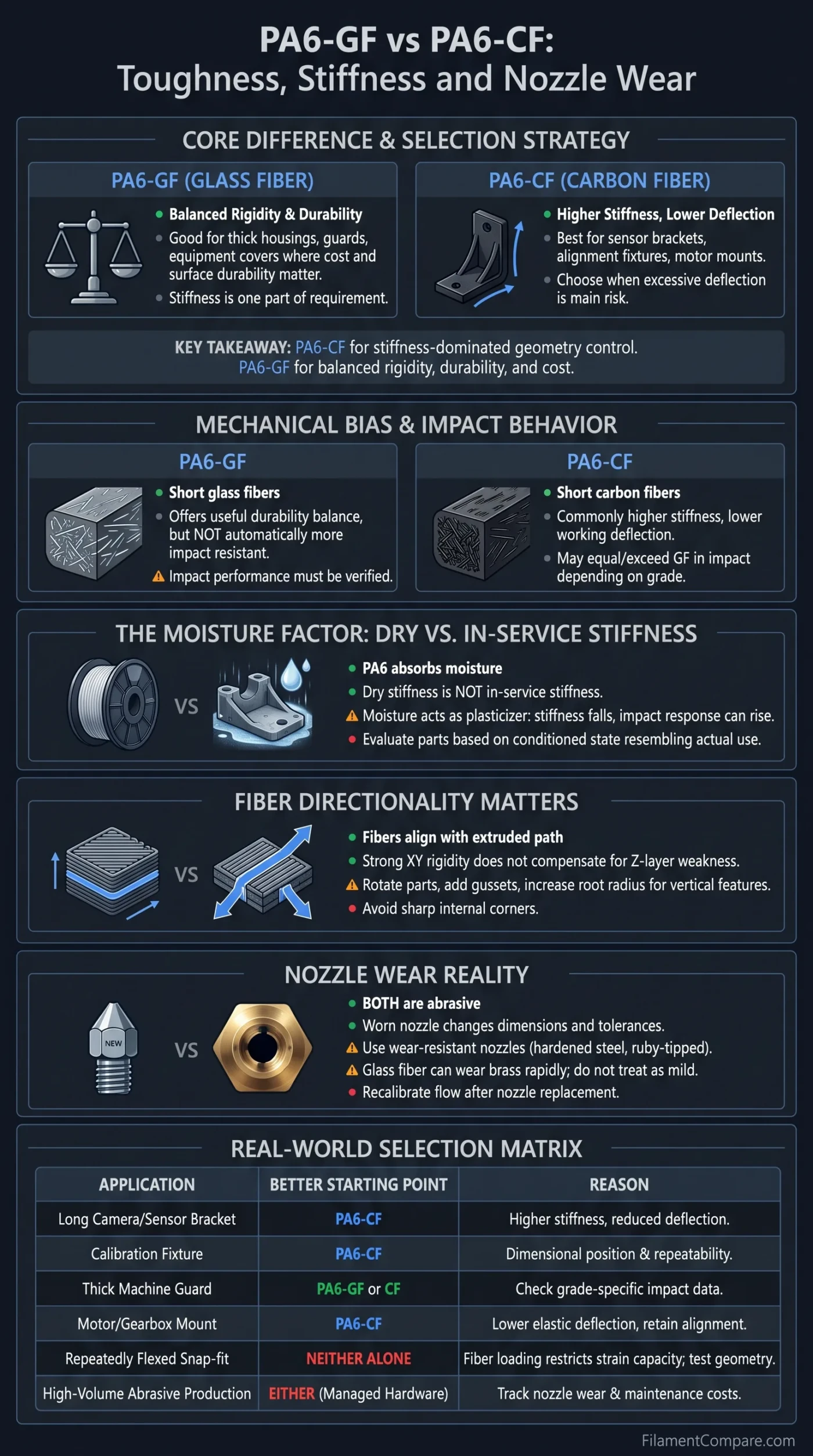
PA6-CF is normally the better starting point when a printed part must resist bending, while PA6-GF can make more sense when the design needs a less stiffness-dominated balance of rigidity, durability, weight and cost. That distinction is not universal: fiber percentage, fiber length, moisture condition, print direction and annealing can change the result enough to reverse a simple “GF for toughness, CF for stiffness” rule.
The Better Fit by Failure Mode
Choose PA6-CF when excessive deflection is the main risk. It is commonly better suited to sensor brackets, alignment fixtures, motor mounts and long structural arms that must hold their geometry under load.
Choose PA6-GF when stiffness is only one part of the requirement. It can be a practical fit for thicker housings, guards, equipment covers and industrial parts where material cost, surface durability and resistance to handling damage also matter.
Neither fiber name guarantees better impact resistance or layer strength. Those properties must be checked on the technical data sheet for the exact grade being purchased.
Both materials use PA6 as the polymer matrix, but their short fibers change how the molten filament flows, shrinks and transfers load. The comparison is therefore less about choosing between two unrelated nylons and more about deciding which reinforced PA6 failure pattern is easier to manage in the intended part.
| Decision Point | PA6-GF | PA6-CF |
|---|---|---|
| Reinforcement | Short glass fibers dispersed through a PA6 matrix | Short carbon fibers dispersed through a PA6 matrix |
| Typical mechanical bias | Balanced rigidity and durability, depending heavily on glass content and formulation | Higher stiffness and lower working deflection are common formulation goals |
| Best reason to choose it | A thick functional part needs reinforcement without making maximum rigidity the only priority | A loaded part must retain alignment, angle or dimensional position |
| Impact behavior | May offer a useful durability balance, but is not automatically more impact resistant | May equal or exceed a GF grade in tested impact strength when the formulation and moisture condition differ |
| Bending resistance | Usually reinforced well beyond unfilled PA6, but often below an equivalent CF-focused grade | Commonly the stronger candidate where elastic bending must be minimized |
| Thin tabs and clips | Still vulnerable to stress concentration and layer-direction failure | High rigidity can make thin flexing details less forgiving |
| Long-term loading | Suitable grades can resist creep, though working deflection must be tested | Often preferred for fixtures, brackets and supports held under continuous load |
| Moisture sensitivity | High; absorbed moisture can lower stiffness and alter dimensions | High; carbon reinforcement does not remove the PA6 matrix’s moisture response |
| Print direction | Fiber alignment favors deposited paths rather than automatically reinforcing Z-layer bonds | Strong XY rigidity does not compensate for a poorly oriented bolt ear or vertical tab |
| Part weight | Glass-filled grades are often denser, though the exact difference is grade-dependent | Can offer a better stiffness-to-weight balance in moving assemblies |
| Surface character | May show a lighter, coarser or more visibly fiber-filled finish | Often produces a dark, matte surface with visually subdued layer lines |
| Nozzle requirement | Wear-resistant nozzle required for sustained printing | Wear-resistant nozzle required for sustained printing |
| Nozzle-wear risk | Glass-filled filament can wear brass rapidly; it should not be treated as a mild additive | Carbon-filled filament is also abrasive, with wear rate affected by fiber content and nozzle material |
| Main selection mistake | Assuming GF always means tougher or less brittle | Assuming the stiffest material will survive every impact, clip motion or Z-direction load |
The Fiber Changes How the Part Fails
Strength, stiffness and toughness describe different responses. A material can carry a high tensile load yet flex more than the application allows. Another can resist bending very well but crack when a thin corner receives an impact. Calling either filament simply “stronger” hides the distinction that matters during part design.
Stiffness controls elastic movement. It matters when a camera angle must remain fixed, a sensor gap cannot change, a motor shaft must stay aligned or a fixture must locate a workpiece repeatedly. A PA6-CF grade with a high tensile or bending modulus is often favored in these cases because the part moves less before reaching its strength limit.
Toughness describes how much energy a part can absorb before fracture. It matters around impact zones, notches, screw bosses, thin transitions and parts that may be dropped. Toughness cannot be inferred from fiber type alone because the PA6 formulation, fiber-matrix bonding, test direction, notch geometry and moisture level all influence the measured result.
PA6-GF Mechanical Character
- Reinforced well beyond standard unfilled PA6
- Often useful for thick industrial bodies and protective structures
- May retain a more forgiving balance than a very stiff CF formulation
- Higher glass loading can also raise rigidity and reduce elongation
- Impact performance must be verified rather than assumed
PA6-CF Mechanical Character
- Usually selected to limit bending and improve geometric control
- Well suited to long brackets, fixtures and alignment-sensitive components
- Can deliver high tensile and flexural modulus
- Thin flexing features may become less tolerant of strain
- Impact behavior varies more by grade than the CF label suggests
A same-manufacturer comparison shows why generic labels should not replace grade data. Fiberon PA6-GF25, containing 25% glass fiber by weight, lists a dry XY Young’s modulus of 5,356.9 MPa and dry notched Charpy impact strength of 10.0 kJ/m²[a].
The corresponding Fiberon PA6-CF20 grade, containing 20% carbon fiber, lists a dry Young’s modulus of 8,636 MPa and dry notched Charpy impact strength of 11.0 kJ/m²[b]. In this product pair, the carbon-filled grade is not only stiffer; it also has a slightly higher published dry notched-impact value. That does not establish a rule for every PA6-CF and PA6-GF filament, but it does disprove the idea that the GF label automatically identifies the tougher option.
Formulation warning: PA6-GF15, PA6-GF25 and PA6-GF30 are not interchangeable material classes. The same applies to PA6-CF grades with different fiber loadings, fiber lengths and coupling systems. A comparison is most useful when both data sheets use the same test standard, specimen direction and conditioning method.
Dry Stiffness Is Not the In-Service Stiffness
PA6 absorbs moisture from its environment. The fibers reduce some forms of movement and shrinkage, but they do not seal the nylon matrix. As moisture enters the polymer, it acts as a plasticizer: stiffness and tensile strength usually fall, while elongation and impact response can rise. A part tested immediately after drying can therefore behave differently after weeks in a humid workshop.
The effect is large enough to change material rankings. In the Fiberon data, PA6-GF25 Young’s modulus falls from 5,356.9 MPa in the dry condition to 1,793.6 MPa after the supplier’s wet-conditioning procedure. Its notched Charpy value moves in the opposite direction, from 10.0 to 28.0 kJ/m². PA6-CF20 moves from 8,636 to 2,508 MPa in Young’s modulus, while its notched Charpy value rises from 11.0 to 35.6 kJ/m².
This does not mean wet filament should be printed. Moisture in the spool during extrusion can cause bubbling, rough surfaces, unstable flow and weaker bonding. The useful distinction is between dry filament during printing and a finished part conditioned by its service environment.
Two Different Moisture Problems
- Moisture before extrusion: Creates processing defects and makes mechanical results less predictable.
- Moisture after printing: Changes the mechanical state of the finished PA6 matrix even when the print was produced correctly.
A dry-room fixture, an outdoor equipment bracket and a coolant-area machine guard should not be evaluated from the same modulus value. Tight fits, bearing seats, bolt spacing and alignment surfaces should be checked after the part has reached a moisture condition that resembles actual use.
This is particularly important when a PA6-CF part is chosen because of its low deflection. The dry-data advantage may remain, but the working part can still become far more compliant than the first bench test suggests. For a continuously loaded assembly, creep testing under expected temperature and humidity is more informative than comparing only dry tensile strength.
Fiber Direction Can Outweigh the GF/CF Label
Short fibers tend to align with the extruded road as material passes through the nozzle. This helps explain why reinforced PA6 can be highly rigid within the printed plane while remaining weaker across layer interfaces. The fibers strengthen the deposited path; they do not form continuous reinforcement running vertically through the complete model.
A long bracket printed flat may use PA6-CF effectively because the main fibers and perimeters follow the load path. The same bracket printed upright can place the highest tensile stress across layer boundaries. In that orientation, changing from GF to CF may provide less benefit than rotating the model, enlarging the root radius or redesigning the joint.
Long Sensor Bracket
Likely better fit: PA6-CF. Low bending deflection helps preserve sensor angle and spacing when the bracket is printed with its long load path in XY.
Thick Impact Cover
Likely better fit: grade-dependent. PA6-GF may offer a useful cost and durability balance, but published impact data should decide the choice.
Vertical Bolt Ear
Fiber name does not solve the weak direction. Rotate the part, add a gusset, increase the root radius or use a joint that keeps tension away from Z layers.
Repeatedly Flexed Clip
Neither reinforced grade is automatically ideal. High fiber loading can restrict strain capacity, making geometry tests or a less rigid nylon formulation more suitable.
Stress concentration becomes more important as stiffness rises. Sharp internal corners, abrupt wall changes, countersunk screws and thin sections beside thick bosses can force a rigid composite to fail locally. A generous fillet or gradual thickness transition may improve the part more than moving to a filament with a higher modulus.
Holes also need separate treatment. A tightly torqued fastener can create radial stress around a printed bore, while a threaded insert can split layers if the surrounding wall is too thin. PA6-CF can hold a fixture accurately, but its extra stiffness should be paired with adequate edge distance, washers, controlled torque and enough material around inserts.
Useful test geometry: Print a small section containing the actual bolt hole, insert, wall thickness and print orientation. A generic tensile coupon cannot reveal splitting around a heat-set insert or cracking at the root of a project-specific mounting ear.
Nozzle Wear Can Erase the Dimensional Advantage
Both glass-filled and carbon-filled PA6 are abrasive. A printer may continue extruding after a soft nozzle begins to wear, so the first symptom is not always a failed print. The opening gradually grows or loses its circular shape, changing extrusion width, corner definition, hole clearance and wall thickness.
This creates a direct contradiction in tolerance-sensitive work: PA6-CF may be selected because it holds a rigid geometry, yet a worn nozzle can introduce process variation before the part leaves the printer. The nozzle becomes part of the dimensional tolerance stack.
Glass fiber should not be treated as the nozzle-friendly alternative. Polymaker states that a brass nozzle has a lifespan of about nine printing hours with its PA6-GF25 formulation and recommends a more durable nozzle[c]. That figure is specific to the supplier’s material and test conditions, but it illustrates how quickly a GF compound can consume a standard brass orifice.
For PA6-CF20, the manufacturer recommends a wear-resistant nozzle such as hardened steel or a ruby-tipped design[d]. The practical rule is therefore the same for both materials: the printer should be configured as an abrasive-filament system rather than temporarily equipped for one difficult spool.
Signs the Nozzle Is Changing
- Calibration cubes grow wider over repeated production runs
- Small holes close more than the established compensation predicts
- Outer walls become heavy despite unchanged flow settings
- Seams and corners appear softer or more swollen
- Extrusion exits at a slight angle after cleaning
- A known profile requires repeated flow reduction
Maintenance That Protects Tolerances
- Use a nozzle designed for abrasive composites
- Record material consumption instead of relying only on print hours
- Keep one reference part for periodic dimensional comparison
- Inspect the orifice before tolerance-sensitive production
- Recalibrate flow after replacing the nozzle
- Separate experimental abrasive printing from validated production hardware when possible
A larger nozzle is often easier to manage with fiber-filled materials because it gives short fibers and the polymer melt a less restrictive flow path. A 0.6 mm wear-resistant nozzle is a practical starting point for thick functional walls, faster deposition and reduced clog sensitivity. A 0.4 mm nozzle can still be appropriate when the filament manufacturer supports it and the model depends on smaller details.
Nozzle diameter does not determine abrasion resistance. A large brass nozzle can still wear rapidly, while a properly manufactured wear-resistant 0.4 mm nozzle may remain stable for much longer. Material loading, fiber shape, flow rate, total kilograms printed and nozzle construction all affect service life.
Print Setup and Annealing Change the Comparison
The printability difference between PA6-GF and PA6-CF is often smaller than the difference between two commercial formulations. Some grades are designed for a cool build plate and open chamber, while others need a warm enclosed environment. A generic “all nylon requires the hottest possible chamber” profile can work against a material engineered around controlled low-bed-temperature crystallization.
For the current Fiberon PA6-GF25 and PA6-CF20 examples, the manufacturer lists a 280–300°C nozzle range and a 40–50°C build plate range, with no heated chamber required. These values should not be copied to a PA6 composite from another supplier without checking its documentation.
Hardware Both Materials Commonly Need
- All-metal hotend capable of the specified PA6 processing temperature
- Wear-resistant nozzle
- Filament dryer that can maintain the required temperature
- Dry feed path during long prints
- Build surface and adhesive compatible with the selected grade
Process Variables That Change the Result
- Filament moisture before printing
- Part orientation and perimeter direction
- Nozzle wear and actual extrusion width
- Chamber and build-plate temperature
- Cooling fan use
- Annealing and post-anneal conditioning
Annealing can raise crystallinity and improve heat performance, but it may also alter dimensions. A flat plate can bow, a circular bore can become oval and a press fit can tighten or loosen. Parts requiring annealing should be designed around the post-annealed state rather than measured only when they first leave the build plate.
The same-manufacturer example also shows why published heat values need their test conditions. PA6-GF25 is listed with an HDT of 191°C at 0.45 MPa, while PA6-CF20 is listed at 215°C under the same nominal load level. Those values describe prepared test specimens, not a guarantee that a thin printed bracket will carry its full room-temperature load at those temperatures.
Heat exposure combines with moisture, load and geometry. A motor mount near a warm enclosure wall may survive the temperature without melting but still creep enough to lose belt alignment. The material decision should therefore consider working deflection at temperature rather than treating HDT as a continuous-use rating.
Dimensional warning: Anneal a representative test piece before committing to a tight-tolerance assembly. Use the same orientation, wall structure, infill strategy and thermal cycle planned for the final component.
Choosing by Failure Mode, Geometry and Maintenance
The useful question is not whether glass fiber or carbon fiber is better in isolation. It is which material reduces the most likely failure without creating a harder problem elsewhere. The table below treats material choice as a part-level decision rather than a ranking of filament labels.
| Part or Requirement | Better Starting Point | Reason | Condition to Check |
|---|---|---|---|
| Long camera or sensor bracket | PA6-CF | Higher stiffness can reduce angular movement and vibration-induced deflection | Orient primary perimeters along the bracket and test the root around mounting holes |
| Calibration fixture or drill guide | PA6-CF | Dimensional position and repeatability usually matter more than impact compliance | Control nozzle wear, moisture conditioning and annealing distortion |
| Thick machine guard | PA6-GF or PA6-CF | Both can work; wall design and grade-specific impact data may matter more than peak modulus | Compare weight, cost, surface requirements and likely impact direction |
| Protective equipment housing | Grade-dependent | A housing needs both rigidity and resistance to corner or drop damage | Test the assembled shell with screw bosses, openings and real wall thickness |
| Motor or gearbox mount | PA6-CF | Lower elastic deflection helps retain shaft, pulley and belt alignment | Evaluate creep at working temperature and bolt preload |
| Repeatedly flexed snap-fit | Neither by label alone | Fiber loading can restrict elongation and concentrate strain at the clip root | Compare actual elongation data or test a less rigid nylon grade |
| Clamp held under constant tension | PA6-CF | Stiffness can reduce opening and loss of clamping geometry | Long-duration creep and humidity may control the real result |
| Large flat tooling plate | Formulation-dependent | Warp-control technology, print temperature and annealing behavior may outweigh fiber type | Use the exact supplier profile and measure the plate after conditioning |
| Fast-moving robot component | PA6-CF | A favorable stiffness-to-weight balance can reduce moving mass and deflection | Do not thin the part until impact and fatigue margins have been tested |
| High-volume abrasive production | Either with managed hardware | Nozzle life, dryer capacity and repeatable maintenance can cost more than the filament difference | Track kilograms printed, dimensional drift and nozzle replacement intervals |
Where the Decision Lands
- Choose PA6-CF when the part fails functionally before it breaks because bending, vibration or alignment drift becomes unacceptable.
- Choose PA6-GF when a thick functional component needs reinforced PA6 performance but maximum stiffness-to-weight is not the main target.
- Compare exact grades when impact resistance is the deciding property. Fiber type alone cannot identify the tougher material.
- Either can work for housings, guards and general machine components when geometry, moisture and print orientation are controlled.
- Neither solves poor load orientation. A vertical bolt ear, thin clip root or sharp internal corner may need redesign before it needs a different fiber.
- Treat both as abrasive. A wear-resistant nozzle and a repeatable inspection schedule belong in the material cost calculation.
PA6-CF is the clearer choice when a designer can identify excessive movement as the expected failure. PA6-GF becomes more attractive when the part needs a broader balance of reinforcement, durability and production cost. The most reliable selection comes from matching a specific technical data sheet, conditioned test part and nozzle-maintenance process to the real geometry rather than selecting by the letters printed on the spool.
Technical Sources and Documentation
- [a] Fiberon™ PA6-GF25 – Fiberon 3D Printing Filament by Polymaker (Used for glass-fiber content, dry and wet mechanical properties, heat-deflection data, printing conditions and the product-specific brass-nozzle statement.)
- [b] Fiberon™ PA6-CF20 – Fiberon 3D Printing Filament by Polymaker (Used for carbon-fiber content, dry and wet mechanical properties, heat-deflection data and printing conditions.)
- [c] Fiberon™ PA6-GF25 – Nozzle Compatibility (Used for the manufacturer’s product-specific estimate for brass-nozzle life.)
- [d] Fiberon™ PA6-CF20 – Nozzle Compatibility (Used for the wear-resistant-nozzle recommendation.)
