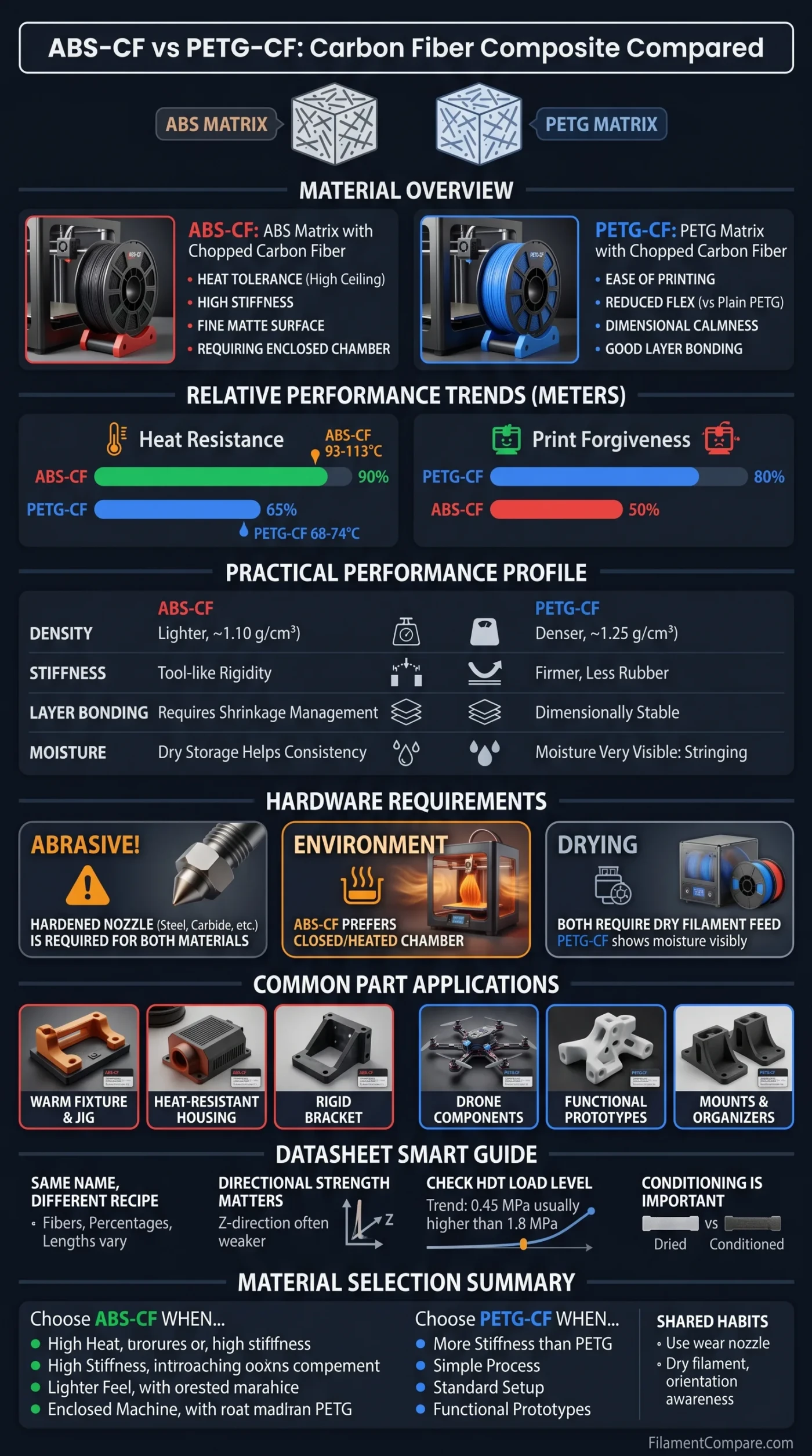
| Comparison Point | ABS-CF | PETG-CF | Practical Reading |
|---|---|---|---|
| Base Polymer | Acrylonitrile butadiene styrene with chopped carbon fiber; Stratasys ABS-CF10 lists 10% chopped carbon fiber by weight [a] | Polyethylene terephthalate glycol with carbon fiber; Flashforge PETGCF10 is listed as a PETG modified material containing 10% carbon fiber [d] | Both are short-fiber filled thermoplastics, but the polymer matrix changes heat behavior, layer bonding, and print setup. |
| Representative Density | About 1.10 g/cm³ in UltiMaker Method ABS-CF data [b] | About 1.25 g/cm³ in Bambu PETG-CF data [c] | ABS-CF often gives a slightly lighter part at the same printed volume; infill and wall count still matter more than spool density alone. |
| Typical Stiffness Pattern | Usually stronger in the stiffness-first category, especially when printed with controlled chamber conditions. | Still much stiffer than plain PETG, with a more forgiving print profile in many desktop setups. | Carbon fiber raises rigidity in both, but it does not erase the base polymer’s character. |
| Heat Deflection Trend | Representative ABS-CF datasheets show roughly 93–113°C depending on method, load, and orientation. | Representative PETG-CF datasheets often sit around 68–74°C for HDT-style figures. | ABS-CF is the stronger heat candidate; PETG-CF fits moderate-temperature functional parts. |
| Layer Bonding Feel | Can produce very rigid parts when the chamber and shrinkage are managed well. | Often easier to keep dimensionally calm on printers that already handle PETG well. | For thin clips, tabs, and mixed-stress shapes, print orientation is not a small detail. It can change the result. |
| Moisture Sensitivity | Lower moisture concern than nylon-based CF blends, but dry storage still helps consistency. | Drying is more visible in print quality; PETG-CF can show more stringing, texture change, or rough extrusion when moisture is present. | Both reward dry storage. PETG-CF tends to make moisture easier to notice during printing. |
| Hardware Needs | Hardened nozzle, stable heatbed, and enclosure are usually part of a clean ABS-CF workflow. | Hardened nozzle and dry filament are the main hardware points; enclosure helps but is not always as central. | Carbon fiber is abrasive in both materials, so brass nozzles are not the ideal long-run match. |
| Common Part Fit | Jigs, fixtures, brackets, housings, tool holders, and parts that need heat plus rigidity. | Drone parts, mounts, covers, practical prototypes, fixtures, and parts that need rigidity plus easier printing. | ABS-CF leans toward thermal stability; PETG-CF leans toward simpler processing and balanced toughness. |
The comparison below uses ABS-CF and PETG-CF manufacturer datasheets plus reliable material references; the values describe tested trends, while real printed parts can shift with brand recipe, fiber loading, nozzle size, chamber temperature, moisture, orientation, and slicer settings.
ABS-CF and PETG-CF look similar on the spool: dark, matte, slightly technical, and packed with short carbon fibers. Their printed parts do not behave the same. The real difference sits in the polymer matrix. ABS-CF starts with an ABS base, so it is usually chosen when heat resistance and stiffness matter. PETG-CF starts with PETG, so it keeps much of PETG’s easier printing feel while gaining a firmer, more textured composite character.
The short version is simple. ABS-CF is more heat-focused. PETG-CF is more printer-friendly for many users. That does not make one universally above the other. It only means they solve different material problems.
Material Pattern in Plain Words
- ABS-CF suits parts where stiffness, a lighter feel, and higher heat tolerance sit near the top of the requirement list.
- PETG-CF suits parts where rigidity is needed, but the printer setup should remain closer to normal PETG practice.
- Carbon fiber improves stiffness and surface texture, yet it usually reduces stretch compared with the unfilled base polymer.
- Orientation still matters because FFF/FDM printed parts are layered, not molded as one continuous block.
Base Polymer and Fiber Content
Carbon fiber does not turn ABS and PETG into the same material. It acts more like a reinforcing phase inside a thermoplastic body. The fiber adds stiffness, texture, and dimensional control, while the base polymer still controls softening temperature, shrinkage behavior, layer fusion, and chemical feel.
ABS-CF: ABS Matrix with Chopped Carbon Fiber
ABS-CF is an ABS-based composite. The ABS matrix gives the material its familiar engineering-plastic profile: heat tolerance, firm structure, and a slightly lower density than many PETG-CF blends. The carbon fiber makes the material feel more rigid and less bendy than plain ABS. Parts often come out with a fine matte surface, and edges can look crisp when the machine is tuned well.
The trade pattern is mostly about print control. ABS-based materials respond strongly to temperature gradients, so ABS-CF commonly prefers an enclosed or heated build environment. It likes stable heat. A lot.
PETG-CF: PETG Matrix with Chopped Carbon Fiber
PETG-CF is a PETG-based composite. PETG already has good layer bonding behavior, useful toughness, and a calmer shrinkage profile than ABS. Carbon fiber changes the feel: the filament prints with a more technical texture, reduced gloss in many blends, and higher rigidity than plain PETG.
PETG-CF is often selected when a user wants less flex than PETG without moving into a higher-temperature ABS workflow. It is not just “PETG in black.” The fiber fill changes extrusion, nozzle wear, and surface behavior.
Mechanical Performance in Real Printed Parts
Datasheet numbers are useful, but they must be read with care. Printed carbon fiber composites are directional. A tensile bar printed flat can behave differently from the same material printed upright, and a wall-aligned toolpath may show a different modulus from a mostly infill-driven test bar.
| Property Area | ABS-CF Pattern | PETG-CF Pattern | Reading for Printed Parts |
|---|---|---|---|
| Tensile Strength | Often around the low 30s to near 50 MPa in representative printed test data, depending on orientation and brand. | Often around the mid 30s to low 40s MPa in common PETG-CF datasheets. | Both can serve functional parts; geometry, walls, and layer direction can outweigh a small datasheet difference. |
| Elastic Modulus | Usually stronger in stiffness when printed under suitable ABS conditions. | Higher than plain PETG, but often not as stiffness-led as ABS-CF. | For brackets and fixtures, stiffness can be more relevant than peak strength. |
| Elongation | Typically low, especially compared with unfilled ABS. | Usually higher than many ABS-CF examples, but still reduced compared with plain PETG. | Carbon fiber composites are chosen more for shape control than stretch. |
| Impact Response | Can feel rigid and firm; thin features should be oriented with load path in mind. | Can keep a more forgiving PETG-like character in many shapes, especially where small flex helps. | Short fibers add stiffness, but they do not replace smart wall direction. |
Stiffness and Tensile Strength
Stiffness is where carbon fiber makes the clearest visual and tactile difference. A PETG-CF part feels less rubbery than plain PETG. An ABS-CF part often feels even more tool-like, especially in thicker sections. This is why both materials appear in fixtures, mounts, gauge holders, and brackets.
Strength is more complicated. A printed part can fail at a layer line, at a notch, near a hole, or along a thin tab. One datasheet number does not describe all of that. Geometry does the talking.
Layer Direction Changes the Numbers
FFF/FDM printing creates a layered part. The road of melted plastic, the raster angle, the wall count, and the Z direction all shape the final behavior. UltiMaker’s ABS-CF data, for example, separates XY, YZ, and Z orientations and notes that Z-direction strength is often the lower direction in FFF printing. That detail is easy to overlook, yet it explains why two users can print the “same” material and get different results.
For ABS-CF vs PETG-CF, this means the better material on paper may not be the better part in hand. A PETG-CF bracket printed with clean layer bonding can outperform a poorly controlled ABS-CF bracket in a load path that crosses layers. The opposite can happen in a warm fixture where ABS-CF stays firmer.
Impact Behavior and Break Pattern
Carbon fiber raises rigidity, but it can also make a material less stretchy. The part may feel more precise and less flexible. Nice for a gauge holder. Less ideal for a snap tab that needs to bend many times.
PETG-CF tends to keep more of PETG’s practical toughness, while ABS-CF leans toward a firmer and more heat-stable feel. Thin clips, hinges, and living-spring shapes need careful testing in both materials because short-fiber composites are not designed around elastic flex.
Relative Trend: Heat Resistance
Relative Trend: Print Forgiveness
Heat Resistance and Dimensional Stability
Heat is one of the cleanest separators between these two composites. ABS-CF usually has the higher heat ceiling. PETG-CF can hold shape in everyday warm environments, but its HDT values are commonly closer to PETG-family behavior than ABS-family behavior.
That matters for parts near motors, LEDs, warm electronics, car interiors, heated shop areas, or fixtures exposed to repeated handling in a warm workspace. A few degrees can matter. So can load.
| Term | What It Means | Why It Matters in This Comparison |
|---|---|---|
| HDT | Heat deflection temperature under a specified load. | ABS-CF usually has the higher value, which helps loaded parts stay straighter when warm. |
| Tg | Glass transition temperature, where an amorphous polymer region becomes softer and more rubbery. | ABS-CF often has a higher Tg region than PETG-CF, supporting better warm-use stiffness. |
| Vicat Softening | A needle-penetration softening test used in thermoplastic datasheets. | It helps compare softening behavior, but it is not the same as a finished part’s service limit. |
| CTE | Coefficient of thermal expansion. | Carbon fiber can reduce expansion and shrinkage, which helps both materials hold shape more predictably. |
HDT, Tg, and Service Temperature
HDT values should never be read without the test load. HDT at 0.45 MPa is not the same as HDT at 1.8 MPa. A PETG-CF value around 70°C can still be useful for many fixtures and covers, while an ABS-CF value above 90°C gives more room for loaded warm-use parts.
Service temperature is a softer idea than HDT. It depends on the load, exposure time, wall thickness, infill, stress concentration, and whether the part is being bent, clamped, or simply sitting in place. Datasheets guide selection; they do not replace testing.
Printing Conditions and Hardware Fit
The printer setup often decides which material feels sensible. ABS-CF prefers a controlled environment. PETG-CF usually fits more easily into printers already tuned for PETG, although it still needs composite-aware hardware.
Chamber Control
ABS-CF benefits from an enclosure because the ABS matrix can shrink as it cools. Carbon fiber helps reduce movement, but it does not make ABS behave like PETG. Corners, long parts, and tall thin walls still prefer stable heat.
PETG-CF is usually calmer on open or semi-enclosed printers. It may string if too hot or too wet, and it may need fan tuning, but the basic thermal stress pattern is often easier to manage than ABS-CF. Simple does not mean careless.
Drying and Storage
PETG-CF often shows moisture more visibly than ABS-CF. Bubbles, rougher surface texture, extra stringing, and weaker-looking extrusion can appear when the filament has absorbed moisture. Dry filament makes the comparison fairer.
ABS-CF also benefits from sealed storage. Clean, dry feeding gives steadier extrusion and better surface finish. For both materials, the spool condition is part of the material, not a side issue.
Nozzle and Drive Wear
Carbon fiber filled filament is abrasive. Prusa’s composite material guidance states that carbon, glass, and kevlar fibers are highly abrasive and require a hardened nozzle [e]. This applies to both ABS-CF and PETG-CF. Hardened steel, ruby-tipped, tungsten carbide, or other wear-resistant nozzles are common matches.
A 0.4 mm hardened nozzle can work with many blends, but a 0.6 mm nozzle often gives more flow room and fewer clogging concerns with fiber-filled materials. The correct choice depends on fiber length, brand, layer height, surface target, and nozzle system.
Printer fit matters: ABS-CF is often the better match for an enclosed, higher-temperature machine. PETG-CF is often the smoother match for a printer already producing clean PETG parts with a hardened nozzle and dry storage.
Surface Finish, Weight, and Part Feel
Both materials can print with a technical, matte or satin surface. Carbon fiber breaks up the plastic shine and can hide layer lines better than plain glossy PETG or ABS. The exact finish varies by brand. Some PETG-CF blends keep a slight sheen; many ABS-CF blends look flatter and more industrial.
ABS-CF often feels lighter and drier in the hand. PETG-CF can feel a bit denser and tougher. These are small differences on tiny prints, but they become noticeable on larger brackets, housings, covers, and fixtures.
Surface quality also depends on moisture, nozzle wear, flow calibration, and cooling. A worn brass nozzle can slowly enlarge and make both materials look less accurate. The spool may be good. The nozzle may be the problem.
Use Case Match by Part Type
For a clean material choice, start from the part’s job. Temperature, load direction, stiffness, and machine setup are more useful than brand names alone.
| Part Type | ABS-CF Fit | PETG-CF Fit | Reason |
|---|---|---|---|
| Warm Fixture or Jig | Very strong candidate | Good for moderate warmth | ABS-CF usually offers more thermal headroom. |
| Drone or RC Component | Useful when heat and stiffness are central | Very useful for rigid, lighter-duty impact-aware parts | PETG-CF balances rigidity and easier print handling. |
| Electronics Housing | Good when chamber printing is available | Good when easy dimensional control is preferred | Both can make clean housings; heat exposure decides the safer direction. |
| Snap-Fit Tab | Use with careful geometry and orientation | Often more forgiving, still needs testing | Carbon fiber reduces stretch; PETG matrix may keep more useful give. |
| Tool Holder | Excellent for rigid shop parts | Excellent for practical shop parts | Both materials are good here; printer setup may decide. |
| Large Flat Panel | Works best with thermal control | Often easier to keep flat | ABS-CF can manage heat better; PETG-CF can manage print stress more easily. |
Reading Datasheets Without Overreading Them
A carbon fiber composite datasheet is not a promise that every printed part will match the test bar. It is a controlled reference. The material, printer, layer height, raster direction, chamber, and conditioning all shape the values.
Same Name, Different Recipe
Two spools labeled ABS-CF can have different fiber percentages, fiber lengths, additives, flow modifiers, and recommended temperatures. The same is true for PETG-CF. A 10% carbon fiber blend does not automatically behave like a 15% blend, and recycled carbon fiber blends may feel different from virgin chopped fiber blends.
Printed Test Bars Are Directional
Datasheets may list XY, XZ, YZ, or Z values. These are not decorative labels. They describe how the test specimen was printed. A part loaded along continuous roads of plastic can perform very differently from a part loaded across layer lines.
HDT Load Level
When comparing heat resistance, check whether the HDT value was tested at 0.45 MPa or 1.8 MPa. The lower-load value is usually higher. Mixing them in one comparison makes the material look better than it may be under heavier load.
Conditioning and Drying
Some datasheets test dried material, some mention conditioning, and some give printer-specific profiles. A wet PETG-CF spool and a dry PETG-CF spool can feel like different materials. ABS-CF also prints cleaner when storage is controlled.
Material Selection Notes for ABS-CF vs PETG-CF
Choose ABS-CF when the part needs a higher heat margin, high stiffness, a lighter composite feel, and the printer can keep ABS-family materials stable. It fits enclosed machines, heated chambers, rigid fixtures, warm jigs, and shop parts where dimensional control under heat is the main pressure.
Choose PETG-CF when the part needs more stiffness than PETG, a cleaner composite surface, and a print process that stays closer to normal PETG. It fits functional prototypes, covers, mounts, brackets, organizers, drone parts, RC parts, and fixtures that do not sit near the upper heat range of ABS-CF.
For small rigid parts, both can work well. For warm loaded parts, ABS-CF usually has the stronger thermal argument. For a desktop printer without tight chamber control, PETG-CF often feels more practical.
- Most Heat-Focused Choice
- ABS-CF, when the printer can manage enclosure and temperature stability.
- More Forgiving Composite Choice
- PETG-CF, especially for users already comfortable with PETG.
- Shared Requirement
- Wear-resistant nozzle, dry storage, and print-orientation awareness.
- Data Habit Worth Keeping
- Compare the exact datasheet for the brand being printed, not only the material name.
