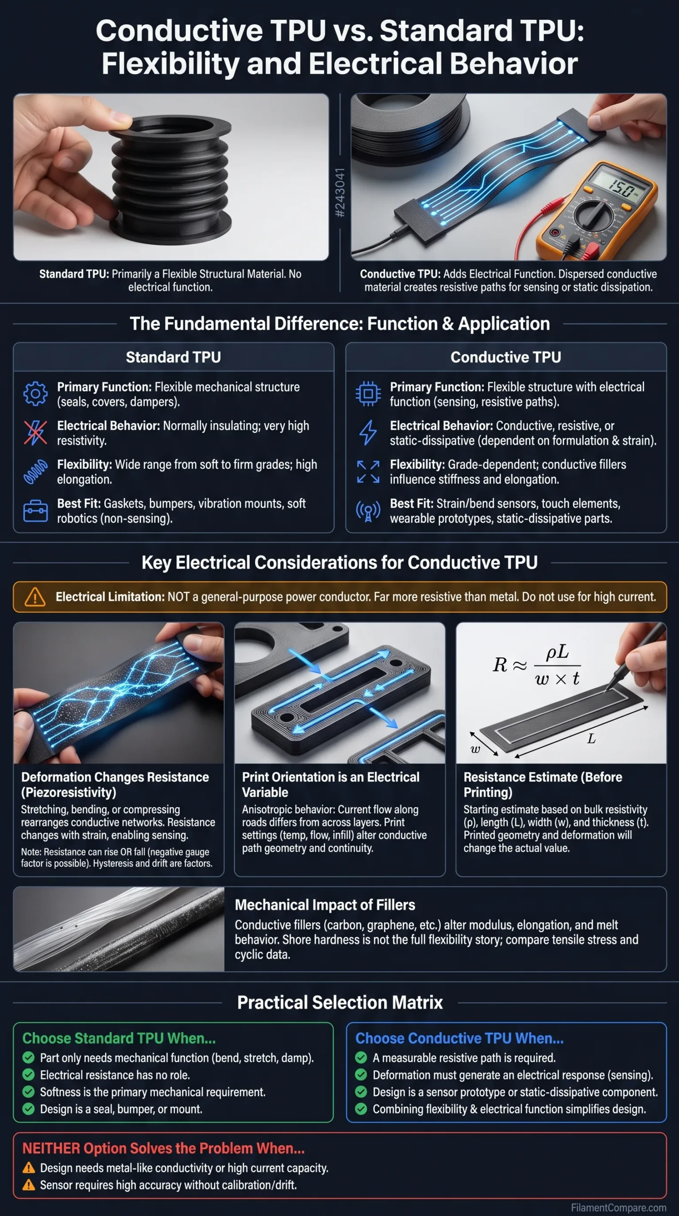
Standard TPU is primarily a flexible structural material, while conductive TPU adds an electrical function by dispersing conductive material through an elastic polymer matrix. The important choice is therefore not simply which TPU bends more: it is whether the printed part needs only mechanical flexibility or must also carry a measurable electrical signal. Conductive grades can sense deformation, form resistive paths or provide static-dissipative behavior, but those capabilities introduce variables that ordinary TPU parts usually do not have.
Where Each TPU Makes Sense
Choose standard TPU for flexible mechanical parts such as seals, protective covers, vibration-damping components, flexible mounts and soft structures that do not need electrical behavior.
Choose conductive TPU when resistance itself is useful: flexible sensing elements, pressure or bend detection, touch interfaces, wearable prototypes, static-dissipative parts or short low-current conductive paths.
Do not treat conductivity as a general upgrade. A conductive filler can change stiffness, elongation, electrical stability and print behavior, and the printed part’s resistance can depend on geometry, orientation and deformation.
| Decision Point | Standard TPU | Conductive TPU |
|---|---|---|
| Primary function | Flexible mechanical structure | Flexible structure with an electrical function |
| Electrical behavior | Normally insulating; conventional TPU grades can have very high surface and volume resistivity[a] | Conductive, resistive or static-dissipative depending on formulation |
| Flexibility | Available from very soft to comparatively firm grades | Also grade-dependent; conductivity does not define a single hardness level |
| Elongation | Can be very high in soft grades | Can remain high, but conductive filler and formulation influence the result |
| Resistance during deformation | Usually irrelevant to the mechanical purpose of the part | May change with stretch, compression or bending |
| Print orientation | Mainly influences mechanical properties and surface behavior | Can influence both mechanical and electrical behavior |
| Trace geometry | Usually a mechanical design variable | Length and cross-sectional area also affect resistance |
| Electrical calibration | Not normally required | Often useful for sensing or repeatable resistive applications |
| Best fit | Gaskets, cases, dampers, flexible joints, soft components | Strain sensors, bend sensors, touch elements, flexible circuits, ESD-oriented parts |
| Power transmission | Not electrically conductive | Generally far more resistive than a metal conductor; suitability is application- and grade-dependent |
| Material consistency | Mechanical properties still vary by TPU grade | Electrical properties add another formulation-dependent variable |
| Main trade-off | No built-in electrical functionality | Greater functional capability, but more dependence on material formulation, geometry and print conditions |
Conductive Fillers Change More Than Electrical Resistance
Standard TPU is not one fixed material. TPU families cover a broad hardness range and combine softer and harder polymer segments in different proportions. That is why two filaments carrying the TPU label can behave very differently under bending, stretching or compression even before conductive additives enter the comparison.
Conductive TPU keeps an elastomeric TPU matrix but introduces electrically conductive material such as carbon black, graphite, graphene, carbon nanotubes or other conductive systems. The electrical path comes from contacts and near-contacts between those conductive regions rather than from ordinary TPU suddenly behaving like copper.
Why filler concentration matters
At low conductive-filler loading, particles may remain too isolated to form a useful path through the polymer. As the conductive phase becomes sufficiently connected, a network can develop through the material. This transition is commonly described using the idea of a percolation network.
More conductive material does not automatically mean an ideal flexible filament. Changing the conductive phase can also alter modulus, elongation, melt behavior and the way the material recovers after deformation.
This is why “conductive TPU” should be treated as a material category rather than a single mechanical specification. Commercial examples already span noticeably different hardness levels. Recreus lists Conductive Filaflex at 92A Shore hardness and describes its electrical resistance as adjustable through printing parameters.[d] NinjaTek, by comparison, specifies its conductive Eel filament at 60D rather than presenting conductive TPU as one fixed softness class.
Conductive, static-dissipative and low-resistance are not interchangeable terms
The word conductive does not tell you enough about a filament to design an electrical part. A grade intended to bleed away static charge can have a very different resistance from a material intended for a resistive sensor, and both are far removed from the conductivity of copper wire.
Electrical limitation: A conductive TPU part that can operate as a sensor, touch contact or static-dissipative component should not automatically be treated as a general-purpose power conductor. Current, voltage, trace dimensions, heat generation and the filament manufacturer’s electrical data all matter.
Shore Hardness Does Not Tell the Whole Flexibility Story
Shore hardness is useful, but it describes resistance to indentation rather than every aspect of flexibility. It does not directly tell you how far a printed strip can stretch, how much force is required at a given strain, how quickly the part returns to shape or how it behaves after hundreds of loading cycles.
A standard flexible filament illustrates the distinction. NinjaTek specifies NinjaFlex at 85A Shore hardness with 660% elongation in its product data.[b] Those two values describe different material properties: 85A is not another way of saying 660% stretch.
The same caution is even more important when comparing conductive and non-conductive TPU. NinjaTek lists conductive Eel at 60D with 355% elongation.[c] This does not prove that conductive TPU as a category is less flexible than standard TPU; it shows why two named grades must be compared using their own mechanical data rather than a general rule about conductive filler.
For a Flexible Mechanical Part
- Check Shore hardness on the correct Shore scale.
- Compare tensile stress at useful strain levels, not hardness alone.
- Look at elongation at break when large deformation matters.
- Consider elastic recovery and permanent set for parts that repeatedly flex.
- Use fatigue or cyclic data when the part will move thousands of times.
For a Flexible Electrical Part
- Check the same mechanical properties.
- Add resistance or resistivity to the specification.
- Measure resistance while the part is deformed.
- Check whether loading and unloading produce the same response.
- Test repeated cycles if resistance will be interpreted as a sensor signal.
For this comparison, flexibility is a mechanical response, not a filament label. A soft standard TPU may be the better choice for a highly compliant seal, while a firmer conductive grade may be more useful when the part needs dimensional stability around an electrical sensing path.
Stretching Conductive TPU Can Change the Circuit Itself
The defining difference appears when a conductive TPU part is deformed. For a simple conductor with resistivity ρ, length L and cross-sectional area A, resistance can be expressed as:
R = ρL / A
Making a conductive trace longer tends to increase its resistance. Increasing its cross-sectional area tends to reduce resistance. A stretched flexible trace can become longer and thinner at the same time, so geometry alone can change the measured value.
Conductive TPU adds another mechanism. Stretching, bending or compressing the polymer can rearrange conductive particles and alter the paths through which charge moves. Some conductive contacts may separate, new contacts may form, and tunneling distances between particles can change. The electrical response therefore comes from both part geometry and the changing conductive network inside the material.
Resistance change is useful when deformation is the signal
This behavior makes conductive TPU useful for piezoresistive sensing. A 2024 study printed strain sensors from NinjaTek Eel conductive TPU and measured electrical resistance during cyclic mechanical loading, directly examining the relationship between strain and resistance in printed TPU sensors.[e]
Sensor response is often expressed using gauge factor:
GF = (ΔR / R0) / ε
R0 is the starting resistance, ΔR is the resistance change and ε is mechanical strain. A gauge factor is meaningful only with the test conditions and usable strain range attached to it; it should not be treated as a universal property of all conductive TPU.
The resistance does not have to rise when the part stretches
A simple mental model says that stretching separates conductive particles and therefore raises resistance. That behavior is possible, but it is not universal. A 2026 study of FDM-printed conductive TPU bend sensors reported a negative gauge factor: resistance decreased during the tested deformation because the conductive pathways and geometry evolved in a different way.[h]
This makes the direction of resistance change something to measure rather than assume. Filament formulation, print path, sensor shape, loading mode and contact arrangement can all influence whether resistance rises, falls or behaves nonlinearly.
Hysteresis and drift separate a sensor from a simple conductive strip
If resistance at 10% strain depends on whether the part is currently being stretched or released, the sensor has hysteresis. If the unloaded baseline changes after repeated cycling, it has drift. Both matter when resistance is being translated into position, force or strain rather than used only to detect a simple on/off event.
Preconditioning can also matter. A freshly printed sensor may not reproduce exactly the same response after it has been stretched repeatedly. For measurement applications, several controlled loading cycles followed by calibration are more informative than a single multimeter reading on a new print.
Print Orientation Becomes an Electrical Design Variable
Material-extrusion printing does not create an electrically uniform block in the same way that an ideal bulk-material equation assumes. A print is assembled from deposited roads and stacked layers, creating interfaces along and between extrusion paths.
A 2024 study examining 14 commercially available conductive polymer composites found anisotropic electrical behavior in material-extrusion printed structures, showing that measured electrical properties can depend on the direction in which current passes through the printed structure.[f]
Along Extrusion Roads
Current can follow conductive material along continuous deposited paths. This may differ electrically from a path that must repeatedly cross bead interfaces.
Across Adjacent Roads
Electrical continuity depends more heavily on contact between neighboring extrusions, making line placement, flow and bonding relevant.
Across Layer Interfaces
A through-thickness path crosses stacked layer boundaries. For some conductive composites, this can produce a different resistance from an in-plane measurement.
Print settings can become electrical settings
With ordinary TPU, extrusion temperature, line width, layer height and flow are usually adjusted to achieve feeding reliability, bonding, surface quality and mechanical performance. With conductive TPU, those same settings can alter the geometry and continuity of the conductive path.
For example, a line that is narrower than expected has less conductive cross-sectional area. Under-extrusion can reduce contact between neighboring roads. Changes in layer bonding can alter the number and quality of interfaces crossed by current. A higher infill percentage may create more conductive paths, but the result still depends on the infill pattern and where the electrical contacts are placed.
Datasheet resistivity is not finished-part resistance. Bulk resistivity describes a material property under defined test conditions. A printed trace adds length, cross-section, extrusion orientation, interlayer contacts, electrode contact resistance and possible deformation. Measure the printed geometry that will actually be used.
A useful resistance estimate before printing
If a manufacturer provides volume resistivity, a simple first estimate can be made with R = ρL/A. For a rectangular printed trace, cross-sectional area is approximately width multiplied by thickness:
Estimated trace resistance: R = ρL / (w × t)
- ρ = material volume resistivity
- L = conductive path length
- w = printed path width
- t = printed path thickness
This is a starting calculation, not a substitute for measurement. Printed conductive TPU can depart from the bulk estimate because the material is not perfectly homogeneous after extrusion and its resistance may change under strain.
Conductive TPU Is Most Useful When Resistance Adds Information
Conductive TPU is easiest to justify when electrical behavior is part of what the printed object is supposed to do. Using it for an ordinary flexible bumper or gasket adds electrical complexity without giving that mechanical part an obvious advantage.
| Application | Better Starting Point | Why | Condition to Check |
|---|---|---|---|
| Flexible gasket or seal | Standard TPU | Elastic deformation is the required function; conductivity normally adds no benefit | Match hardness, compression behavior and chemical exposure to the application |
| Protective case or bumper | Standard TPU | Impact absorption and flexibility matter more than resistance | Wall geometry can influence softness as much as filament hardness |
| Vibration-damping mount | Standard TPU | The design is primarily mechanical | Evaluate cyclic deformation and permanent set |
| Strain-sensing strip | Conductive TPU | Resistance change can provide a measurable response to deformation | Calibrate strain, resistance, hysteresis and repeatability |
| Flexible bend sensor | Conductive TPU | A printed resistive element can respond to changing geometry | Do not assume that resistance must increase with bending |
| Pressure-sensitive element | Conductive TPU | Compression can alter conductive contacts and measured resistance | Characterize the exact part geometry and loading direction |
| Wearable sensing prototype | Conductive TPU | Mechanical compliance and electrical response can exist in the same printed feature | Skin-contact suitability cannot be inferred from conductivity alone |
| Soft robot body | Usually standard TPU | Flexible movement can be produced without adding a resistive material | Conductive TPU becomes useful when self-sensing is also required |
| Soft robot sensing section | Conductive TPU | The deforming structure can also act as a sensing element | Signal drift and repeated-cycle behavior need testing |
| Static-dissipative component | Specified conductive or dissipative TPU | Controlled electrical resistance is part of the requirement | Verify the grade’s actual resistance range rather than relying on the word “conductive” |
| Low-resistance power wiring | Neither as a default choice | Metal conductors normally provide much lower resistance | Calculate voltage drop, current and heating before considering a conductive polymer path |
NinjaTek describes Eel as both flexible and static-dissipative and positions it for applications including robotics and small LEDs. That is a useful example of how a commercial conductive TPU can occupy a specific electrical niche rather than serving as a universal flexible conductor.
Printed flexible sensors are now being treated as systems, not just materials
A 2026 systematic review of 3D-printed flexible strain sensors evaluated 76 experimental studies and compared material systems, printing routes, architectures, gauge-factor reporting, signal stability and durability.[g] The useful lesson for conductive TPU is that filament selection is only one layer of sensor performance. Geometry, manufacturing route and electrical measurement design can change the result enough that comparing spool specifications alone is incomplete.
Choosing by Part Requirement
Practical Selection Matrix
Choose standard TPU when…
- the part only needs bending, stretching, damping or impact absorption;
- electrical resistance has no functional role;
- you want to select softness primarily from mechanical requirements;
- you do not want deformation to become an electrical variable;
- the design is a seal, bumper, flexible mount, soft enclosure or similar mechanical component.
Choose conductive TPU when…
- the printed part must provide a measurable resistive path;
- deformation itself needs to generate an electrical response;
- the design is a strain, bend, pressure or touch-sensing prototype;
- static-dissipative behavior is required and the selected grade has suitable specifications;
- combining flexibility and electrical function in one printed feature simplifies the design.
Either type can work mechanically when…
- both specific grades meet the required hardness, elongation and recovery behavior;
- conductivity neither helps nor interferes with the actual part requirement.
Neither option fully solves the problem when…
- the design needs metal-like conductivity or substantial current carrying capacity;
- a sensor must provide accurate measurements without calibration or repeatability testing;
- the electrical requirement has not been defined beyond the word “conductive.”
The most useful distinction is therefore functional rather than categorical. Standard TPU is primarily chosen for controlled mechanical deformation; conductive TPU is chosen when that deformation must coexist with an electrical response. For conductive parts, filament formulation is only the starting point—the printed geometry, current direction, strain state and contact method become part of the electrical design.
Technical Sources and Documentation
- [a] Electrical properties | Technology by Covestro (Used for conventional TPU insulation behavior, surface resistivity and volume resistivity.)
- [b] NinjaFlex 3D Printer Filament (85A) (Used for the manufacturer-listed 85A Shore hardness and 660% elongation example.)
- [c] Eel 3D Printer Filament (60D) (Used for the conductive TPU hardness, elongation and application information.)
- [d] Conductive Filaflex (Used for the 92A conductive TPU example and manufacturer statement that electrical resistance can be adjusted through printing parameters.)
- [e] Electrical Resistance Response to Strain in 3D-Printed Conductive Thermoplastic Polyurethane (TPU) (Used for cyclic strain and resistance behavior in an FDM-printed conductive TPU sensor.)
- [f] Characterization of the Anisotropic Electrical Properties of Additively Manufactured Structures Made from Electrically Conductive Composites by Material Extrusion (Used for print-direction-dependent electrical behavior in material-extrusion conductive composites.)
- [g] A Systematic Review of 3D-Printed Flexible Strain Sensors: Materials, Architectures, and Performance (Used for the current research context connecting material choice with sensor architecture, printing route and performance.)
- [h] Geometrically Optimized FDM-Printed Conductive TPU Bend Sensors for Hand Rehabilitation (Used for the 2026 example showing a negative gauge factor in a conductive TPU bending sensor.)
